Honeywell T8400C Installation Instructions - Page 2
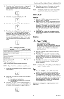
Mounting Decorator Cover Plate and, Wallplate to Wall, Wiring - thermostat
 |
View all Honeywell T8400C manuals
Add to My Manuals
Save this manual to your list of manuals |
Page 2 highlights
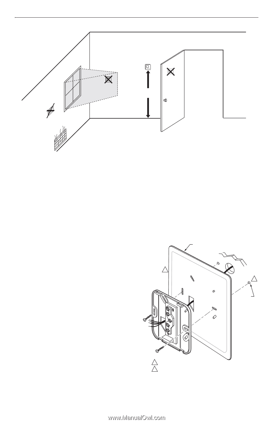
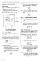
T8400C AND T8401C ELECTRONIC THERMOSTATS YES NO NO 5 FEET [1.5 METERS] NO M10308 Fig. 1. Typical location of thermostat. Mounting Decorator Cover Plate and Wallplate to Wall IMPORTANT Level only for appearance. The thermostat functions normally even when not level. NOTE: Only SUPER TRADELINE® models have the cover plate. Mount decorator cover plate (SUPER TRADELINE® model only), wallplate, T8400C or T8401C, and the screws provided (see Fig. 2) as follows: 1. Place the desired decorator cover plate and the wallplate at the desired location on the wall. 2. Pull the thermostat wire through the entrance hole on the decorator cover plate, then through the wallplate entrance hole. 3. Select the two mounting holes that best fit the application. 4. Fasten the decorator cover plate and the wallplate to the wall using the anchors and screws provided. 5. After wiring the wallplate, plug the hole to prevent drafts from affecting the thermostat; see Wiring section. The shape of the terminals permits insertion of straight or wraparound wiring connections; either method is acceptable. See Fig. 4. The T8400C Thermostat is powered through the heating/ cooling system controls and is adaptable to most 4-wire, 18 to 30 Vac heating-cooling systems. The T8401C Thermostat is powered directly from the system transformer and is adaptable to most 5-wire, 18 to 30 Vac heating-cooling systems. Refer to Fig. 5 and 6 for typical wiring hookups. 5-3/4 IN. x 5-3/4 IN. DECORATOR COVER PLATE WALL 1 2 WALL ANCHORS (2) Wiring IMPORTANT Use an 18-gauge maximum wire for wiring the T8400C and T8401C Thermostats. All wiring must comply with local electrical codes and ordinances. Disconnect the power supply to prevent electrical shock or equipment damage. NOTE: To ensure proper mounting of thermostat, restrict all wiring to the shaded area on the left side of the terminals. See Fig. 3. 1 3-7/8 IN. x 3-7/8 IN. DECORATOR COVER PLATE (SELECT MODELS). 2 DRILL 3/16 INCH HOLES (IF DRYWALL) OR 7/32 (PLASTER OR WOOD) WHEN USING WALL ANCHORS. M11041C Fig. 2. Mounting decorator cover plate and wallplate to wall. 69-1480-1 2
-
 1
1 -
 2
2 -
 3
3 -
 4
4 -
 5
5 -
 6
6
 |
 |