Hoover L2310 Manual - Page 4
Installation, How to use - the guv
 |
UPC - 073502027288
View all Hoover L2310 manuals
Add to My Manuals
Save this manual to your list of manuals |
Page 4 highlights
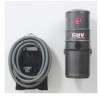
2. Installation Mounting location The GUV™ power unit can be mounted in the garage, basement, utility room, or any other remote area, except where exposed to weather, and no more than 5 feet from an electrical outlet. Because this unit requires ventilation, DO NOT install in a heat producing or confined area such as the attic, furnace room, etc. The top of the GUV™ power unit should be no less than 12" (30.5 cm) from the ceiling, and any corner wall to allow proper cooling of the motor. For ease of removing the dirt container, the bottom of the unit should be at least 18" (46 cm) above the floor. DO NOT block the two small inlet holes located above each latch holder. Because the top surface of the GUV™ power unit gets hot during operation, DO NOT place or store any objects on top of the unit. UNDER NO CIRCUMSTANCES SHOULD AN EXTENSION CORD BE USED WITH THIS APPLIANCE. 5) Hose rack (drywall or plaster wall): Drill a 1/4" (.64 cm) dia. x 1-1/4" (3.18 cm) pilot hole. Insert the anchor drywall mount into the hole. Mount the hose rack from an eye on one side with a screw. Make sure the rack is straight. Drill a second pilot hole using the second eye on the rack. Insert the anchor drywall mount into the hole. Fasten tightly with the other screw. Hose rack (block or concrete wall): follow instructions under 3) for mounting the GUV™ power unit bracket. 6) Plug the power cord in. 4 Mounting the GUV™ power unit and hose rack 1) Determine if the wall you will be mounting the GUV™ power unit to is block, concrete, or plaster/drywall. 2) Drywall or Plaster Wall (fasteners included) GUV™ power unit: Locate a stud and drill a 9/64" (.36 cm) dia. x 1-1/4" (3.18 cm) pilot hole. Mount the bracket from the top center hole with a screw. Making sure that the bracket is straight, drill a second pilot hole using the lower hole on the bracket as a guide and fasten tightly with the other screw. If no stud is available, drill a 1/4" (.64 cm) dia. x 1-1/4" (3.18 cm) pilot hole and use anchor drywall mounts. 3) Block or Concrete Wall (fasteners are not included) GUV™ power unit: You will need (2) 1-1/2" (3.8 cm) x 1/4" (.64 cm) lead plugs and (2) 1-1/2" (3.8 cm) x 1/4" (.64 cm) lag bolts. Drill a 1/2" (1.3 cm) dia. x 1-3/4" (4.4 cm) deep hole with a masonry drill bit. Insert a lead plug into the hole. 3. How to use Insert the hose into the hose inlet as shown in Fig. 3-1. The GUV™ power unit is turned ON and OFF with the switch found on the upper section of the motor module. 3-1 2-1 TOP MOUNTING BRACKET Mount the bracket (Fig. 2-1) from a top corner hole with a lag bolt. Mark the other top corner hole of the bracket. Make sure that the bracket is straight. Slide the bracket away from the mark and drill a hole directly over the mark. Insert a lead plug into the hole. Align the bracket over the hole and tightly fasten with a lag bolt. Continue to 4). 4) Mount the GUV™ power unit on the bracket making sure the bar on the back of the machine is settled to the bottom of the slots on the mounting bracket. The wall mounting bracket must fit between the two brackets on the back of the GUV™ power unit. 3-2 A C B C D E Selecting the proper tool A. Dusting brush may be used for work benches, vehicle interiors, baseboards, lighting fixtures, etc. B. Furniture nozzle may be used for vehicle interiors, carpeted stairs, mattresses, etc. C. Crevice tools may be used in tight spaces, corners and along edges in such places as vehicle interiors, drawers, upholstered furniture, stairs and baseboards. D. Floor nozzle may be used to clean garage and basement floors and other floor surfaces. E. Wands are used to give extra length to the hose. Use them with any of the above tools. They are especially useful with the floor nozzle.
-
 1
1 -
 2
2 -
 3
3 -
 4
4 -
 5
5 -
 6
6 -
 7
7
 |
 |
