Hunter 20531 Owner's Manual
Hunter 20531 Manual
 |
View all Hunter 20531 manuals
Add to My Manuals
Save this manual to your list of manuals |
Hunter 20531 manual content summary:
- Hunter 20531 | Owner's Manual - Page 1
and Warranty Assistance For reference, also attach your receipt or a copy of your receipt to the manual. Model Name Model No. Catalog No. Date Purchased Where Purchased Type 2 Models Owner's Guide and Installation Manual English Español Form# 42450-01 20101118 ©2010 Hunter Fan Co. - Hunter 20531 | Owner's Manual - Page 2
Cleaning Your Ceiling Fan 16 9 • Troubleshooting 17 Cautions and Warnings • READ THIS ENTIRE MANUAL CAREFULLY BEFORE BEGINNING INSTALLATION. SAVE THESE INSTRUCTIONS. • Use only Hunter replacement parts. • To reduce the risk of personal injury, attach the fan directly to the support structure of - Hunter 20531 | Owner's Manual - Page 3
and safe for your new Hunter fan. If you cannot check off every item, prepare a new fan site as described on this page. Fan Support System • Fan attaches directly to building structure. • Fan support system will hold full weight of the fan and light kit. Ceiling Hole • e outlet box clearance hole - Hunter 20531 | Owner's Manual - Page 4
support service panel. 5-2. read the fan supply line through the outlet box so that the fan supply line extends at least 6" beyond the box. 5-3. Attach the fan ceiling fan site. For instructions to install your ceiling fan, go to your fan manual and continue with Section 2 • Installing the Ceiling - Hunter 20531 | Owner's Manual - Page 5
, follow the instructions included with each product. For quiet and optimum performance of your Hunter fan, use only Hunter speed controls. Support Brace Ceiling Outlet Box For ceilings higher than 8 feet, you can purchase Hunter extension downrods. All Hunter fans use sturdy 3/4" diameter - Hunter 20531 | Owner's Manual - Page 6
site) Checking Your Fan Parts Carefully unpack your fan to avoid damage to the fan parts. Refer to the included Parts Guide. Check for any shipping damage to the motor or fan blades. If any parts are missing or damaged, contact your Hunter dealer or call Hunter Technical Support Department at 888 - Hunter 20531 | Owner's Manual - Page 7
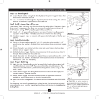
into the wood support structure through the outermost holes in the outlet box. The pilot holes should be 9/64" Ceiling in diameter. Plate 2-2. Your fan comes with two neoprene noise isolators ("Isolators"). Position the isolators between the ceiling plate and ceiling by inserting the raised - Hunter 20531 | Owner's Manual - Page 8
. Go to 4 • Wiring the Fan. WARNING: Fan may fall if not assembled as directed in these installation instructions. Steps 3-1 - 3-2 Setscrew Steps 3-3 - 3-4 Ceiling Plate Tabs Step 3-5 Downrod Canopy Low Profile Washer #8-32 x 1" Screw Canopy Slots 8 42450-01 • 11/18/10 • Hunter Fan Company - Hunter 20531 | Owner's Manual - Page 9
. 4-6. Turn the splices upward and push them carefully back through the ceiling plate into the outlet box. 4-7. Spread the wires apart, with the grounded wires on one side of the outlet box and the ungrounded wires on the other side of the outlet box. 9 42450-01 • 11/18/10 • Hunter Fan Company - Hunter 20531 | Owner's Manual - Page 10
could cause fan to fall. 5-2. Lift the fan and align the canopy screw holes with the mounting holes on the ceiling plate. 5-3. Partially install a canopy screw into the side opposite the ceiling plate tabs. trim ring from the canopy. Step 5-4 Step 5-5 10 42450-01 • 11/18/10 • Hunter Fan Company - Hunter 20531 | Owner's Manual - Page 11
Blades Hunter fans use several styles of fan blade irons (brackets that hold the blade to the fan). 6-1. Your fan may include blade grommets. If your fan mounting screw through the blade iron, and attach lightly to the fan. Insert the second blade mounting screw, then securely tighten both mounting - Hunter 20531 | Owner's Manual - Page 12
Hunter fan comes with an integrated light fixture assembly and an optional switch housing cap and plug button. This feature gives you the option of installing the fan . WARNING: Use only the light fixture supplied with this fan model. 7-1. To attach the upper switch housing, partially install - Hunter 20531 | Owner's Manual - Page 13
, this ceiling fan contains a device that restricts its light output. Exceeding the wattage limit marked on the MAX wattage sticker affixed to the light socket(s) may result in fire hazard or improper operation. If lights do not appear to be operating properly, see the troubleshooting section - Hunter 20531 | Owner's Manual - Page 14
, Thread the light pull chain throught the hole in the center of the cover plate. 7-12. Thread the fan pull chain through the grommet hole in the side of the cover plate. 7-13. Place the cover plate up Breakaway Connector Glass Bowl Cover Plate Finial 14 42450-01 • 11/18/10 • Hunter Fan Company - Hunter 20531 | Owner's Manual - Page 15
other plug connector (female) through the hole. 7-20. Install the dummy terminals (included in the sack parts) on the two disconnected wires in the lower switch housing. 7-21. Install the switch housing cap and Terminal Cap Plug Button Step 7-21 15 42450-01 • 11/18/10 • Hunter Fan Company - Hunter 20531 | Owner's Manual - Page 16
chain has two settings: ON and OFF. 8-4. Ceiling fans work best by blowing air downward (counterclockwise blade rotation fan off and let it come to a complete stop. Slide the reversing switch on the fan to the opposite position. Restart fan. Reversing Switch 16 42450-01 • 11/18/10 • Hunter Fan - Hunter 20531 | Owner's Manual - Page 17
if the blade is cracked. If so, replace all the blades. Problem: Excessive wobbling. 1. If your fan wobbles when operating, use the enclosed balancing kit and instructions to balance the fan. 2. Tighten all blade iron screws. 3. Turn power off, support fan very carefully, and check that the hanger
-
 1
1 -
 2
2 -
 3
3 -
 4
4 -
 5
5 -
 6
6 -
 7
7 -
8
-
9
-
10
-
11
-
12
-
13
-
14
-
15
-
16
-
17
 |
 |

Type 2 Models
Type 2 Models
Type 2 Models
Form# 42450-01
20101118
©2010 Hunter Fan Co.
For Your Records and
Warranty Assistance
For reference, also attach your receipt or a copy
of your receipt to the manual.
__________________________________________
Model Name
__________________________________________
Model No.
__________________________________________
Catalog No.
__________________________________________
Date Purchased
__________________________________________
Where Purchased
English
Español
Owner’s Guide and Installation Manual