Hunter 23710 Owner's Manual
Hunter 23710 Manual
 |
View all Hunter 23710 manuals
Add to My Manuals
Save this manual to your list of manuals |
Hunter 23710 manual content summary:
- Hunter 23710 | Owner's Manual - Page 1
INSTRUCTIONS FOR HUNTER CEILING FAN TYPE 2 1896 ART NOUVEAU READ AND SAVE THESE INSTRUCTIONS CAUTION! 1. Read entire instructions parts. Step 3: Installation of Outlet Box and Rough-In Wiring CAUTION: Your Hunter ceiling fan ceiling or to an electrical outlet box. Mounting must support a 35 lb. fan - Hunter 23710 | Owner's Manual - Page 2
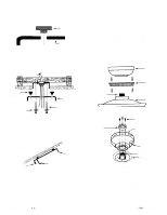
the ceiling plate to the 2 x 4 brace which supports the outlet box. Use (2) #10 wood screws 3" long and (2) flat washers for mounting. Drill (2) pilot holes for mounting screws 9/64" diameter. See Figure 4A. NOTE: Assembly Methods for Installer's Choice Hanging System Your new Hunter fan can - Hunter 23710 | Owner's Manual - Page 3
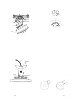
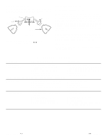
ceiling plate hook. Make sure you do not break any wire connections. The canopy has (3) suspen- sion flanges located on top. See Figure 6. The ceiling plate has (3) mating slots. See Figure 6A. CANOPY CEILING PLATE FLANGE SLOT Figure 6 Figure 6A FORM NO. 41184-01 10/05 -3- ©2005 HUNTER FAN - Hunter 23710 | Owner's Manual - Page 4
ceiling plate. Using (3) 10 -32 x 1/2" long Phillips round head screws, secure the canopy to the ceiling plate. CAUTION: Failure to properly tighten the (3) screws could result in the fan fan. Should the fan wobble in operation, you may use this kit to correct the balance per the instructions problem. - Hunter 23710 | Owner's Manual - Page 5
. See Figure 10. Speed Control As an option, a wall mounted speed control switch is available from your Hunter dealer. TROUBLESHOOTING GUIDE PROBLEM PROBABLE CAUSE 1. Nothing happens fan does not move.* 1. Power turned off or fuse blown. 2. Loose wire connections or wrong connections. 3. Motor - Hunter 23710 | Owner's Manual - Page 6
©2005 HUNTER FAN CO. FORM NO. 41184-01 10/05 -6- H U N T E R F A N C O M- PANY ® 2500 FRISCO
-
 1
1 -
 2
2 -
 3
3 -
 4
4 -
 5
5 -
 6
6
 |
 |
CAUTION!
1.
Read entire instructions before beginning installation.
2. To avoid possible electrical shock, be certain electricity is
shut off at main panel before wiring.
3.
All wiring must be in accordance with national and local elec-
trical codes. If you are unfamiliar with wiring, you should use
a qualified electrician.
WARNING!
1.
To reduce the risk of fire or electrical shock, do not use a solid
state speed control with this fan. Use Hunter Controls only.
2. To reduce the risk of personal injury, do not bend the blade
brackets when installing the brackets or cleaning the fan. Do
not insert foreign objects in between the rotating fan blades.
Step 1: Pre-installation Instructions
A.
Select installation site. Check to see that in normal use no
object can come in contact with the rotating fan blades. The
mounting site should also meet the precautions listed in Step 3
below.
B.
Installation hardware is included for a standard drywall or
plaster ceiling. You will need a 4" x 1-1/2" or 4" x 1/2" outlet box
and wire nuts (2) which can be purchased from any hardware
store or electrical supply house.
C.
The fan blades must be mounted at least 7' above the floor.
For maximum efficiency, they should not have any obstruction
(walls, posts, etc.) within 24" of the blade tips. See Figure 1 for
mounting distances.
Step 2: Inspection of Fan
A.
Unpack the fan carefully to avoid any damage to the
components.
B.
Check for any shipping damage to the motor and the fan
blades. If more than one fan is being installed, keep the matched
and balanced blades in sets, as they were shipped. Should one of
the blades become damaged during shipment, return all blades in
the set for replacement.
C.
Check contents to be certain it contains a bag of parts.
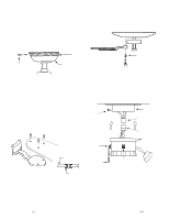
Step 3: Installation of Outlet Box and
Rough —In Wiring
CAUTION:
Your Hunter ceiling fan with accessories can weigh
up to 35 lbs. The following precautions must be taken for safety
and to ensure that your fan is securely mounted to the ceiling. Be
certain electricity is “off” at the fuse panel when inspecting or
repairing installation site. All wiring must meet local and
national electrical codes. Do not mount directly to an unsup-
ported ceiling or to an electrical outlet box. Mounting must sup-
port a 35 lb. fan with accessories.
A.
Secure metallic outlet box 4" x 1-1/2" or 4" x 1/2" deep to 2
x 4 cross brace between two ceiling joists as shown in Figure 2.
The outlet box must be recessed into the ceiling by1/16 "
mini-
mum. Secure the outlet box to the cross brace by drilling (2)
pilot holes no larger than the minor diameter of the wood screws
( 5/64") and use two #8 x 1-1/2" wood screws and washers. Use
the innermost holes for securing the box. Orient the box so the
outermost holes will be used in Step 4B.
CAUTION:
Do not use lubricant on screws.
B.
Bring electrical cable into the outlet box and attach with an
approved connector. Make certain that wiring meets all national
and local electrical codes. Wire leads should extend at least 6"
beyond outlet box for ease in making connections. See Figure 3.
FORM NO. 41184-01 1
0
/
0
5
-
1
-
©
200
5 HUNTERFANCO.
INSTALLATION INSTRUCTIONS
FOR HUNTER CEILING FAN TYPE 2
1896 ART NOUVEAU
READ AND SAVE THESE INSTRUCTIONS
SINCE
1 8 8 6
®
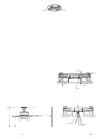
Figure 1. Wall Clearances
Figure 3. Wiring Outlet Box
24”
CLEARANCE
TO
OBSTRUCTIONS
6" MIN.
LEAD LENGTH
7
'
MIN.
TO FLOOR
8
'
MIN.
CEILING
TO FLOOR
2 x 4 BRACE
CEILING
JOIST
OUTLET BOX
CEILING
CONNECTOR
#8 WOOD SCREW &
WASHER (2) REQUIRED
Figure 2. Outlet Box