Hunter 23710 Owner's Manual - Page 4
Step 9: Assemble Switch Housing, Step 8: Fan Blade Assembly, Installation, and Balancing
 |
View all Hunter 23710 manuals
Add to My Manuals
Save this manual to your list of manuals |
Page 4 highlights
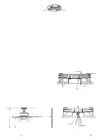
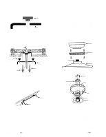
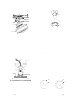
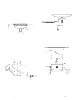
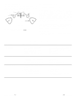
B. Lift the fan and position the (3) flanges in the canopy into the (3) mating slots in the ceiling plate. Lift the fan until it is free to rotate in either direction. Rotate the fan until the (3) larger holes in the canopy line up with the (3) mating holes in the ceiling plate. Using (3) 10 -32 x 1/2" long Phillips round head screws, secure the canopy to the ceiling plate. CAUTION: Failure to properly tighten the (3) screws could result in the fan falling. C. Slide the canopy trim piece up to the top of the canopy and align the (3) holes in the trim with the (3) mating holes in the canopy. Using (3) 6-32 by 3/8" long countersunk head screws assemble the trim to the canopy. See Figure 7. Snug the screws, do not over tighten. B. Remove the screws and rubber bumpers from the motor hub. Insert a mounting screw (provided) in hole in blade bracket. Use a screwdriver to hold in place. Align blade holes with mounting holes in hub by turning screw and readjusting blade bracket until screw mates with threaded hole in hub. Do not tighten until both screws have been put in blade bracket. Repeat for all blades. See Figure 9. ASSEMBLY SCREWS TRIM CANOPY BLADE MOUNTING SCREWS NOTE: MAKE CERTAIN ALL SCREWS ARE TIGHT Figure 9 Figure 7 NOTE: Check the hanger ball and make certain the (2) tabs in the canopy are still engaged with the (2) grooves in the hanger ball before operating the fan. See Figure 5D. If the tabs are not engaged with the ball grooves you will need to re-align the tabs before proceeding. Step 8: Fan Blade Assembly, Installation, and Balancing A. Attach blades to blade brackets using three screws for each blade. See Figure 8. You must first insert the rubber grommets into the holes in the blades. See Figure 8A. NOTE: Grommets are usually assembled by hand. If you use a tool, make certain you do not damage the grommet or blade when inserting the grommets. C. A blade balancing kit has been provided with your fan. Should the fan wobble in operation, you may use this kit to correct the balance per the instructions supplied with the kit. Step 9: Assemble Switch Housing A. Assemble lower switch housing to upper switch housing. See Figure 10. ASSEMBLY SCREWS UPPER SWITCH HOUSING UPPER PLUG CONNECTOR LOWER PLUG CONNECTOR POWER / ON-OFF SWITCH LOWER SWITCH HOUSING BLADE BREAKAWAY CONNECTOR REVERSING SWITCH Figure 8 GROMMET Figure 8A Figure 10 First connect the upper and lower plug connectors. See Figure 10. Next assemble the blade to the blade bracket. Make sure all NOTE: The plug is polarized and will only go together one way. screws are tight to prevent vibration or wobbling. Make sure you have correctly aligned both halves of the connector. NOTE: When the screws are tight, the blades may seem to be loose. This is normal when using grommets and will not be a problem. Next assemble the upper and lower switch housing using (3) 6-32 countersunk head screws. Make sure the (3) holes in both halves of the switch housing line up with each other. You may have to slightly rotate the blades to allow clearance to the assembly screws. Snug the (3) screws, but do not over tighten or you could strip the threads. FORM NO. 41184-01 10/05 -4- ©2005 HUNTER FAN CO.
-
 1
1 -
 2
2 -
 3
3 -
 4
4 -
 5
5 -
 6
6
 |
 |
