Hunter 23980 Owner's Manual
Hunter 23980 Manual
 |
View all Hunter 23980 manuals
Add to My Manuals
Save this manual to your list of manuals |
Hunter 23980 manual content summary:
- Hunter 23980 | Owner's Manual - Page 1
For Your Records and Warranty Assistance Model Name Catalog/Model No Serial No Date Purchased Where Purchased For reference also attach your receipt or a copy of your receipt to the manual. 42405-01 • 01/20/06 - Hunter 23980 | Owner's Manual - Page 2
Your Ceiling Fan 11 9 • Troubleshooting 12 © 2006 Hunter Fan Company Hunter Fan Company Your new Hunter® ceiling fan is an addition to your home or office that will provide comfort and performance for many years. is installation and operation manual gives you complete instructions for installing - Hunter 23980 | Owner's Manual - Page 3
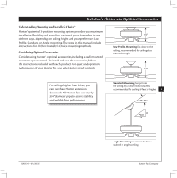
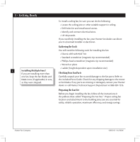
provides you maximum installation flexibility and ease. You can install your Hunter fan in one of three ways, depending on ceiling height and your preference: Low Profile, Standard, or Angle mounting. e steps in this manual include instructions for all three Installer's Choice mounting methods - Hunter 23980 | Owner's Manual - Page 4
missing or damaged, contact your Hunter dealer or call Hunter Technical Support Department at 888-830-1326. Preparing the Fan Site Before you begin installing the fan, follow all the instructions in the pullout sheet called "Preparing the Fan Site." Proper ceiling fan location and attachment to the - Hunter 23980 | Owner's Manual - Page 5
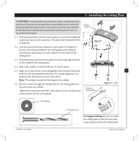
, before installing your fan, disconnect the power by turning off the circuit breakers to the outlet box and associated wall switch location. If you cannot lock the circuit breakers in the off position, securely fasten a prominent warning device, such as a tag, to the service panel. Ceiling Plate - Hunter 23980 | Owner's Manual - Page 6
and Hanging the Fan Steps 3-2 - 3-3 Downrod WARNING: Fan may fall if not assembled as directed in these installation instructions. 3-1. Unbundle the wires from the fan. Canopy For Standard or Angled Mounting: Set Screw 3-2. To assemble fan to hang down from a flat or angled ceiling, insert the - Hunter 23980 | Owner's Manual - Page 7
ground wire from the fan • e white wire from the ceiling to the white wire from the fan • e black wire from the ceiling to the black wire from the fan 4-2. Push all wires and wire nuts into the outlet box. 4 • Wiring the Fan Wire Nut Single Switch Wiring 7 42405-01 • 01/20/06 Hunter Fan Company - Hunter 23980 | Owner's Manual - Page 8
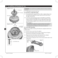
mounting holes on the ceiling plate. 5-3. Partially install a canopy screw into the side opposite the ceiling plate tabs. 5-4. Partially install another canopy screw into the hole between the two ceiling plate tabs. Securely tighten both screws. 8 Step 5-3 Step 5-4 Hunter Fan Company 42405-01 - Hunter 23980 | Owner's Manual - Page 9
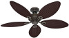
mounting screws are installed in the motor to secure shipping blocks. Remove the blade mounting screws and rubber bumpers from the motor. Save the screws and discard the bumpers. 6-4. For each blade, insert one blade mounting screw through the blade iron, and attach lightly to the fan. Insert the - Hunter 23980 | Owner's Manual - Page 10
housing assembly screws are firmly situated in the narrow end of the keyhole slots. Install the remaining housing assembly screw into the housing. Tighten all three screws firmly. CAUTION screws. Lower Switch Housing Housing Assembly Screw Steps 7-5 - 7-6 Hunter Fan Company 42405-01 • 01/20/06 - Hunter 23980 | Owner's Manual - Page 11
. 8-3. e light pull chain controls power to the light. e pull chain has two settings: On and Off. 8-4. Ceiling fans work best by fan off and let it come to a complete stop. Slide the reversing switch on the fan to the opposite position. Restart fan. Reversing Switch 42405-01 • 01/20/06 Hunter Fan - Hunter 23980 | Owner's Manual - Page 12
blade is cracked. If so, replace all the blades. Problem: Excessive wobbling. 1. If your fan wobbles when operating, use the enclosed balancing kit and instructions to balance the fan. 2. Tighten all blade iron screws. 3. Turn power off, support fan very carefully, and check that the hanger ball is
-
 1
1 -
 2
2 -
 3
3 -
 4
4 -
 5
5 -
 6
6 -
 7
7 -
8
-
9
-
10
-
11
-
12
 |
 |

42405-01 • 01/20/06
For Your Records and Warranty
Assistance
Model Name: _____________________
Catalog/Model No.: ________________
Serial No.: _______________________
Date Purchased: ___________________
Where Purchased: _________________
For reference also attach your receipt or a
copy of your receipt to the manual.