IBM 4840-563 System Reference
IBM 4840-563 Manual
 |
View all IBM 4840-563 manuals
Add to My Manuals
Save this manual to your list of manuals |
IBM 4840-563 manual content summary:
- IBM 4840-563 | System Reference - Page 1
SurePOS 500 Model XX3 Technical System Reference Version: 1.3 SurePOS 500 Model XX3 Technical Reference, v 1.3 Page 1 of 81 - IBM 4840-563 | System Reference - Page 2
/04 Revised copy with Engineering inputs, MSR programming interface 1.2 3/25/04 Updated System Block diagram, Presence sensor status, and ASIC control registers. 1.3 4/1/04 Update Video Memory SurePOS 500 Model XX3 Technical Reference, v 1.3 Page 2 of 81 - IBM 4840-563 | System Reference - Page 3
...21 Chapter 5 Tower Logic ...21 Processor ...21 8245GV Memory Controller Hub, (GMCH 21 I/O Controller Hub, Intel ICH4 ...22 Optional Second Video Adapter...22 Network ...24 Extended POS Features ...24 PC Card Support (Models 553 and 563) ...24 Chapter 6 Power Supply Unit 25 Power Management - IBM 4840-563 | System Reference - Page 4
Appendix D Memory Map ...37 I/O Map ...38 PCI Configuration...40 Interrupt and DMA Assignments ...41 DMA Assignments ...42 Special SurePOS 500-XX3 POS Devices Interfaces 42 Appendix E ASIC PCI Function 1: POS UARTs 46 Appendix F Connectors ...48 Appendix G Input/Output device commands 56 Appendix - IBM 4840-563 | System Reference - Page 5
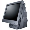
The IBM 4840 SurePOS 500 Series Point of Sale System is designed to drive the POS transactions within your food service, hospitality, petroleum, and specialty retail providers worldwide. SurePOS 500 - Model 563 (LEADERSHIP, MULTIMEDIA) The sleek leadership model of this family displays excellent - IBM 4840-563 | System Reference - Page 6
should read this manual This guide is intended for technical personnel who will plan, install, setup, and operate the point-of-sale terminal. These personnel will also carry out preliminary diagnostic procedures using the information in this manual, before making a service call. SurePOS 500 Model - IBM 4840-563 | System Reference - Page 7
Store Solutions Web site at www.ibm.com/solutions/retail/store/ SurePOS 500 Series Device Drivers SurePOS 500 Series Service Diskette At that site, select Support, then under Software select Download Software Maintenance and select SurePOS 500 Series. SurePOS 500 Model XX3 Technical Reference - IBM 4840-563 | System Reference - Page 8
Chapter 1 Model Specifications Model Summary Model 4840- 533 Processor Dual Video 2.0 GHZ Option Celeron 4840-543 2.0 GHZ Option Celeron Presence Spk Tablet Memory Sensor er No No 12-in 128 Std Single Bulb 256,512,1G, 2GB No Yes 12-in Dual 128 Std 256,512,1G, Bulb - IBM 4840-563 | System Reference - Page 9
Model Specifications 4840-533 4840-543 4840-553 4840-563 Processor Intel Celeron 2.0 GHz PSB Speed Chipset BIOS Main Memory Video 400 MHz ) 2 Cash Drawer 3 Unpowered RS232 1 Powered RS232 (External Customer Display) Headphone/Microphone (553/563premium model only) RJ45 LAN External Floppy - IBM 4840-563 | System Reference - Page 10
systems where the DVMT driver is not available, a second 'pre-allocated' and fixed UMA memory size defined. This pre-allocated memory is set to 8Mb system memory be configured at 256Mb. This is to insure sufficient memory for Operating System, Application, and video usage. SurePOS 500 Model - IBM 4840-563 | System Reference - Page 11
Select Feature Mass Storage Memory LCD Dual Video 40GB HDD or 512 MB Compact Flash (Model 533) 128MB, 256MB, 512 MB, 1GB, 2 GB 12-in or 15-in (Model 563 only) All Models Factory install feature code Optional Features Unless otherwise stated, all features are designated as customer set up and - IBM 4840-563 | System Reference - Page 12
5 Ethernet Cable (4.3m), P/N 42L0098 Serial Cable, RJ45 to DB9 (0.7m), P/N 03R7887 The following items are picked packed per order at IBM Distribution Center: Warranty Sheet Installation, Operations, and Planning (optional with specify code) Regulatory and Safety Messages Booklet (GA27-4004) Power - IBM 4840-563 | System Reference - Page 13
SurePOS 500-XX3 subject to operating restrictions defined in the Operating System support section. Other industry devices may be supported USB not - IBM USB Floppy Drive, P/N 05K9276 supported - IBM USB Keyboard, P/N 10K3849 (OBI on DOS P/N) - IBM Memory Key P/N 22P9025 - IBM 4685-S01/L0H - IBM 4840-563 | System Reference - Page 14
System Software POS Application Interface Drivers POS Application drivers may be more restrictive on operating system support. Refer to the OPOS/JavaPOS specifications for supported operating systems. Operating System POS Application Interface Extensions (MSRs, Customer Displays, Cash Drawer - IBM 4840-563 | System Reference - Page 15
Chapter 3 Architectural Overview SurePOS 500 Model XX3 Technical Reference, v 1.3 81 Page 15 of - IBM 4840-563 | System Reference - Page 16
x 2 pwr button headphone microphone kbd/mouse floppy pc card dual video option Tailgate Tailgate Power Supply HDD signal HDD power HDD/Compact Flash 12v/24v SurePOS 500 Model XX3 Technical Reference, v 1.3 81 Page 16 of - IBM 4840-563 | System Reference - Page 17
Main Board Block Diagram SurePOS 500 Model XX3 Technical Reference, v 1.3 81 Page 17 of - IBM 4840-563 | System Reference - Page 18
Serial: 1. COM1 (Tailgate port A) 2. COM2 (Tailgate port A) 3. COM3 (Tablet, Tablet) 4. COM4 (Int/Ext VFD port) 5. COM5 (Tablet, Touch) 6 COM6 (T il t t C) SurePOS 500 Model XX3 Technical Reference, v 1.3 81 * Note: One CRT Connector on Tailgate is multiplexed between Dual Video Adapter and On - IBM 4840-563 | System Reference - Page 19
Distributed APA Display MSR (3 track or JUCC) 9.5 kg (23 lbs) 11.7 kg (24.5 lbs) 0.21 kg (0.38 lbs) 0.55 kg (1.2 lbs) 0.73 kg (1.6 lbs) 0.16 kg (0.41 lbs) Wallmount 12" N/A N/A N/A 321 364 217 ? N/A N/A 250 ? tbd 311 ? Wallmount 15" N/A N/A N/A 383 426 217 ? N/A N/A 252 ? tbd 320 ? SurePOS 500 - IBM 4840-563 | System Reference - Page 20
Ports, Controls and Indicators Port Location and Marking Front Access Area (rotated) Rear Tailgate DISPLAY SurePOS 500 Model XX3 Technical Reference, v 1.3 81 Page 20 of - IBM 4840-563 | System Reference - Page 21
double sided, x16 DDR sdram supported - Supported DIMM sizes: 128MB, 256MB, 512 MB, 1 GB Integrated Extreme Graphics 3D Controller - 256 bit engine - 64 MB maximum UMA video memory - Synchronous LCD/CRT support - LVDS Panel support Video Support Implementation Notes: SurePOS 500 Model XX3 Technical - IBM 4840-563 | System Reference - Page 22
SurePOS 500-XX3 provides a dual video adapter to allow for true multi-monitor support memory (capable of 8 MB) ? 60, 75, XX Hz refresh rates SVGA CRT output (replaces onboard video out) Supports Windows 98 and 2000 Dual Display Supported . Audio (Models 553 and 563) In combination with the south - IBM 4840-563 | System Reference - Page 23
a volume control on the speaker unit. Bass/Treble slides in windows volume control will not be functional This subsystem can be disabled in through Setup. SurePOS 500 Model XX3 Technical Reference, v 1.3 81 Page 23 of - IBM 4840-563 | System Reference - Page 24
values, MAC address Extended POS Features The Extended POS I/O subsystem is attached to PCI bus and provides support for additional I/O ports sensor port PC Card Support (Models 553 and 563) The PC Card subsystem provides for the capability to attach PC Cards (PCMCIA). SurePOS 500-XX3 provides a - IBM 4840-563 | System Reference - Page 25
Power States APM Off, APM Standby, APM Enabled, Full On ACPI Global States: G0, G1, G2 Sleep States: S0, S1, S5 Power Control SurePOS 500-XX3 supports the following power state changes based upon event: Power On Resume Power Switch Yes Yes LAN Yes Yes Alarm Yes Yes Touch No Yes - IBM 4840-563 | System Reference - Page 26
min.) 1024x1024 0.080-in. 0.047-in. (96%) 0.222-in (4%) Chem Etch 92% N/A None Glass n/A +40, -60 50,000 hrs 11.5 +/- 45 40,000 hrs 11 SurePOS 500 Model XX3 Technical Reference, v 1.3 81 Page 26 of - IBM 4840-563 | System Reference - Page 27
Track 5 W Chapter 8 POS I/O Specifications MSR SurePOS 500-XX3 supports two msr types: 3-Track and JUCC. The SurePOS 500-XX3 3-Track MSR swipes Note 1. The interface is set by customer using switch before installation. Default is RS232. SurePOS 500 Model XX3 Technical Reference, v 1.3 81 Page - IBM 4840-563 | System Reference - Page 28
Speaker Unit SurePOS 500-XX3 supports an external stereo speaker unit. The speaker unit is a self-contained assembly which attaches to SurePOS 500-XX3 using mounting screws. There is a connection provided for input, power and signal, to the speaker unit. The speaker unit contains the drivers and - IBM 4840-563 | System Reference - Page 29
Russian) Code Page 869 (Greece) Logic Controls Mode: 1 IBM Mode: 8 TTL Serial RS232 5V 12V 6W 7.2 W Pigtail 3.8 m (12 ft) SurePOS 500-XX3 supports an integrated and distributed 2x20 customer display. The integrated display mounts externally to the rear cover and provides a 3 position - IBM 4840-563 | System Reference - Page 30
APA Display SurePOS 500-XX3 supports an external all points addressable customer display. This is intended to meet Technology Brightness Vacuum Fluorescent 300 cd/m2 Format (dot) 160 x 40 Active Area (mm) 132.55 x 32.95 Dot Size ( - IBM 4840-563 | System Reference - Page 31
Clear Jumper located near the memory DIMM. Query vital product ibm.com/solutions/retail/store/ SurePOS 500 Series Device Drivers SurePOS 500 Series Service Diskette At that site, select Support, then under Software select Download Software Maintenance and select SurePOS 500 Series. DOS-based service - IBM 4840-563 | System Reference - Page 32
location of the VPD is in the EEPROM attached to the custom SurePOS 500-XX3 ASIC. This information will also be shadowed into the flash ROM at address F000:FFA0 as is standard on all IBM PC's. SurePOS 500XX3 BIOS will implement the IBM standard INT 15h interface for finding the VPD data area within - IBM 4840-563 | System Reference - Page 33
SurePOS 500-XX3 relies on convection cooling so placement requires the ambient air adjacent to the unit does not exceed supported maximums. The vents cannot the cable attached I/O devices such as the distributed customer display or scanners: IBM RSS Chemical Resistance Test NEMA Type 5 rating per - IBM 4840-563 | System Reference - Page 34
cd, msr, 2x20, printer) On (max, printing) 7 Watts Not supported 49 Watts 60 Watts -? 79 Watts 82 Watts Input Voltage/Frequency Maximum IBM C-H 1-9711-005 C-H 1-9711-001 C-H 1-9711-004 A. Acoustics 1. Classification Item Acoustics Category/Class 2B Reference Standard C-S 1-1710-006 SurePOS - IBM 4840-563 | System Reference - Page 35
Zealand EMI Class A Australia EMI Class A IBM C-S 2-0001-012 Bands 1 through 9 EN 50024: 1998 (EN61000-4-3) Criteria A Electrical Fast Transient/Power Line Transient (EFT/PLT) EN 50024: 1998 (EN61000-4-4) Criteria B IBM C-S 2-0001-001 Class 2 SurePOS 500 Model XX3 Technical Reference, v 1.3 81 - IBM 4840-563 | System Reference - Page 36
C-S 2-0001-040 Low Frequency Emissions from Visual Display Units EN50024: 1998 (EN 61000-4-11) IBM C-S 2-4700-033 EN50024: 1998 (EN61000-4-5, Criteria B) IBM C-S 2-0001-022 IBM C-P 2-0001-025 IBM C-B 2-0001-033 EN55024:1998 EN61000-4-6 Criteria A IBM C-B 2-0001-035 EN55024:1998 EN61000-4-8 Criteria - IBM 4840-563 | System Reference - Page 37
Buffer Intel 82845GV Video ROM BIOS (shadowed) PCI/ISA Space, DOS memory managers System ROM BIOS (ISA Bus, main memory shadowed) and USB Legacy space PCI/ISA Space PCI Space subtractive BIOS for PCI devices, A20 Alias of System BIOS SurePOS 500 Model XX3 Technical Reference, v 1.3 81 Page 37 of - IBM 4840-563 | System Reference - Page 38
processor 01F0-01F7 0295-0296 8 bytes 6 bytes IDE Channel 0 (decoded by Intel 82801DB (ICH4)) SMC LPC47M192 Index/Data port for LPC SurePOS 500 Model XX3 Technical Reference, v 1.3 81 REFERENCE Intel 82801DB (ICH4) Intel 82801DB (ICH4) Intel 82801DB (ICH4) Intel 82801DB (ICH4) SMC LPC47M192 - IBM 4840-563 | System Reference - Page 39
SMC LPC47M192 SMC LPC47M192 SMC LPC47M192 Intel 82801DB (ICH4) Intel 82801DB (ICH4) Intel 82801DB (ICH4) SMC LPC47M192 Intel MHC4 and ICH4 Intel MCH4 and ICH4 SurePOS 500 Model XX3 Technical Reference, v 1.3 81 Page 39 of - IBM 4840-563 | System Reference - Page 40
AD(24) AD(25) AD(26) AD(20) Intel Ethernet Controller TI 1211 PCMCIA Controller Secondary Video controller (Cedar card) SurePOS 500-XX3 custom ASIC Fn 0: POS interface/special functions Fn 1: UARTs interace PCI Bus Number PCI Device Number (hex) PCI IO Register Address range (hex) 0 0 0 1Dh - IBM 4840-563 | System Reference - Page 41
dynamic because of Plug-and-Play and PCI configuration. However, some are fixed based on legacy requirements, as shown in the table below. Because the SurePOS 500-XX3 design will make use of the APIC interrupt controller in the ICH4, there will be 20 interrupts instead of 16 as we had - IBM 4840-563 | System Reference - Page 42
pages. Special SurePOS 500-XX3 POS Devices Interfaces ASIC PCI Function 0: POS Interface - special devices Function 0 of the SurePOS 500-XX3 ASIC Registers (16 Bytes of I/O Space) EEPROM (128 Bytes of Memory Space) Reserved (00000000h) Reserved (00000000h) Reserved (00000000h) Reserved - IBM 4840-563 | System Reference - Page 43
-up value as 0. It is used to enable/disable the presence sensor function. The polled Presence Sensor status can be read via the following steps: SurePOS 500 Model XX3 Technical Reference, v 1.3 81 Page 43 of - IBM 4840-563 | System Reference - Page 44
a 0 to bit 0 after the interrupt service is done. This register is a direct 1: Read EEPROM contents into ASIC memory. x x x x x x Y x 1: Write ASIC memory contents into EEPROM. Note that - Disable 1 4 UART 3: 1- Enabled, 0 - Disable 1 SurePOS 500 Model XX3 Technical Reference, v 1.3 81 Page 44 of - IBM 4840-563 | System Reference - Page 45
Control Register (before EEPROM is loaded): 01h Bit 0: Enable/disable PS/2 keyboard on the planar. When bit 0 is set to "1", the keyboard will be enabled. SurePOS 500 Model XX3 Technical Reference, v 1.3 81 Page 45 of - IBM 4840-563 | System Reference - Page 46
Appendix E ASIC PCI Function 1: POS UARTs In the custom ASIC, SurePOS 500-XX3 provides 4 additional 16550 compatible UARTs, one of which is general use and the other 00h 04h 08h 0Ch 10h 14h 18h 1Ch 20h 24h 28h 2Ch 30h 34h 38h 3Ch 40h SurePOS 500 Model XX3 Technical Reference, v 1.3 81 Page 46 of - IBM 4840-563 | System Reference - Page 47
Status (0: No Interrupt, 1: Interrupt Asserted) Bit 1 = Status of UART 1 Interrupt Status (0: No Interrupt, 1: Interrupt Asserted) Bit 0 = Status of UART 0 Interrupt Status (0: No Interrupt, 1: Interrupt Asserted) SurePOS 500 Model XX3 Technical Reference, v 1.3 81 Page 47 of - IBM 4840-563 | System Reference - Page 48
Appendix F Connectors Distributed Customer Display Connector Pin Connector 1 CD (carrier detect) 2 RxD (receive data) 3 TxD (transmit data) 4 DTR (data terminal ready) 5 Ground 6 Line Left 4 Line Right 5 Ground. SurePOS 500 Model XX3 Technical Reference, v 1.3 81 Page 48 of - IBM 4840-563 | System Reference - Page 49
RJ45 Serial Port Connector RJ45 to 9 Pin Cable Wiring SurePOS 500 Model XX3 Technical Reference, v 1.3 81 Page 49 of - IBM 4840-563 | System Reference - Page 50
(TTL) 4 Ground 5 KBD Enable (low enables kybd data to system) 6 Keyboard data 7 Keyboard clock 8 Ground USB port connector (x 6) Pin Connector 1 5V VBus 2 -Data 3 +Data 4 Ground SurePOS 500 Model XX3 Technical Reference, v 1.3 81 Page 50 of - IBM 4840-563 | System Reference - Page 51
(12V or 24V) Vplus (12 or 24V) Ground Keyboard/Mouse connector Pin Signal I/O 1 Keyboard Data I/O 2 Mouse Data I/O 3 Ground Pin Signal I/O 4 +5 V Main 5 Keyboard Clock I/O 6 Mouse Clock SurePOS 500 Model XX3 Technical Reference, v 1.3 81 Page 51 of - IBM 4840-563 | System Reference - Page 52
# I I/O 16 INIT# O I/O 17 SLCT IN# O I/O 18 Ground I/O 19 Ground I/O 20 Ground I/O 21 Ground I/O 22 Ground I 23 Ground I 24 Ground I 25 Ground External Diskette Drive Connector SurePOS 500 Model XX3 Technical Reference, v 1.3 81 Page 52 of - IBM 4840-563 | System Reference - Page 53
the write head. 23 TRK0 I Track 0. Sense to detect that the head is positioned over track 0. 24 WRTPROT I Write Protect. Sense for detection that the SurePOS 500 Model XX3 Technical Reference, v 1.3 81 Page 53 of - IBM 4840-563 | System Reference - Page 54
3 Blue 4 Monitor ID2 - not used 5 Ground 6 Red ground 7 Green ground 8 Blue ground 9 no connector 10 Gound 11 No connector 12 MON ID1 13 Horizontal sync SurePOS 500 Model XX3 Technical Reference, v 1.3 81 Page 54 of - IBM 4840-563 | System Reference - Page 55
14 Vertical Sync 15 MON ID3 Cash Drawer (x2) Pin Connector 1 Ground 2 Sense 3 Open 4 24V Internal Customer Display Pin Connector 1 +5V Main 2 Transmit Data 3 Int VFD Present 4 Ground SurePOS 500 Model XX3 Technical Reference, v 1.3 81 Page 55 of - IBM 4840-563 | System Reference - Page 56
usage for the SurePOS 500 Series I/O Note: This command is only effective in IBM Mode. 02 nn Purpose: Selects the specified 03 nn Purpose: Defines a custom character. Logic Controls Emulation Mode The any occurrence of that character on the display will change to the user-defined character. - IBM 4840-563 | System Reference - Page 57
that it is off. * This is maintained for application compatibility with displays with 5x8 character boxes. ←----5pixelswide ----→ IBM Mode The byte that follows the command byte represents an address between . Horizontal tab (09) SurePOS 500 Model XX3 Technical Reference, v 1.3 81 Page 57 of - IBM 4840-563 | System Reference - Page 58
cursor is on the top line when this command is sent. Vertical Scroll Display Control Mode (DC2) If the cursor is on the top line, it end of the test, the display is cleared and is reset to the power-on state as described at "Reset (1F) " on page 55. SurePOS 500 Model XX3 Technical Reference, - IBM 4840-563 | System Reference - Page 59
to be transferred to the top line. This is the power-on and Reset command default setting. The display remains in DC2 mode until a DC1 mode command is issued. Cursor on (13) 13 : Turns off the cursor. Reset (1F) 1F Purpose: SurePOS 500 Model XX3 Technical Reference, v 1.3 81 Page 59 of - IBM 4840-563 | System Reference - Page 60
Brightness set to 100%. v IBM user-defined characters are not erased display in Logic Controls mode. User-defined characters in the IBM Display Mode v User Definable Font v Graphic Display and the displaying screen is row, the displayed character is scrolled changed. The displayed character under the - IBM 4840-563 | System Reference - Page 61
and Px=1). Delete to end of line 1B 5B 30 4B Dimming Purpose: The displayed characters from the write-in position to the end position on the same row are (X'31') 31.6 Ps Luminance % Appendix E. Input/Output device commands 57 SurePOS 500 Model XX3 Technical Reference, v 1.3 81 Page 61 of - IBM 4840-563 | System Reference - Page 62
Ps in the preceding command format), changes the cursor mode. The cursor is always displayed at the write-in position. The cursor is formed by five dots located at the ') 5x7 dots, 5 rows 8 (X'38') 16x16 dots, 2 rows Horizontal scroll SurePOS 500 Model XX3 Technical Reference, v 1.3 81 Page 62 of - IBM 4840-563 | System Reference - Page 63
Scroll command operates: 1B 5B Ps 6D Purpose: This command sets the display mode characteristics. The control byte embedded in the command sequence (represented by Ps every time you switch on the power. Graphic display mode SurePOS 500 Model XX3 Technical Reference, v 1.3 81 Page 63 of - IBM 4840-563 | System Reference - Page 64
, and Pw in the preceding command format), change the graphic display characteristics. Pd represents the data byte. Double size letter in in horizontal 60 SurePOS 500 Series System Reference Character code set of full size letter ?? Purpose: Can't figure this out from the spec. Character code set - IBM 4840-563 | System Reference - Page 65
represents the data bytes. This command does not affect previous display settings. The format of the Horizontal Scroll Start command is follows: Pn 30: English -IBM code page 437 modified (default) 31: Japanese -JIS X 0208-1990 32: Korean -KS C 5601-1992 SurePOS 500 Model XX3 Technical Reference, - IBM 4840-563 | System Reference - Page 66
cash drawer 1, use the following command, which sends an ASCII Ack character to the customer display serial port. See "Cash drawer status information" for a description of the cash come from a keyboard so no device driver is needed.) SurePOS 500 Model XX3 Technical Reference, v 1.3 81 Page 66 of - IBM 4840-563 | System Reference - Page 67
located so that it is not accessible with the MSR is fully installed is used to reset the MSR's configuration to the factory default state. SurePOS 500 Model XX3 Technical Reference, v 1.3 81 Page 67 of - IBM 4840-563 | System Reference - Page 68
' 9 ' 10 58 0x3A ' : ' 11 59 0x3B ' ; ' 12 60 0x3C ' < ' 13 61 0x3D ' = ' 14 62 0x3E ' > ' 15 63 0x3F ' ? ' Color Key Control values Standard Sentinal values SurePOS 500 Model XX3 Technical Reference, v 1.3 81 Page 68 of - IBM 4840-563 | System Reference - Page 69
Configuration bits Function CR enabled Raw data mode track 1 disabled track 2 disabled track 3 disabled Strip Sentinels Use Custom Configuration Hide Error tracks SS1 SS2 SS3 ES Factory PS/2 1 0 0 0 0 0 0 0 0x25 see ISO-646-US-ASCII. SurePOS 500 Model XX3 Technical Reference, v 1.3 Page 69 of 81 - IBM 4840-563 | System Reference - Page 70
included in the MSR data. Byte 1, Bit 6: Use Custom Configuration This bit defaults to '0'. When this bit is set, the custom configuration in the rest of the configuration word is used. place of the sentinel found in the track data. SurePOS 500 Model XX3 Technical Reference, v 1.3 81 Page 70 of - IBM 4840-563 | System Reference - Page 71
interface is to comply with the in circuit programming specification described in Philips Semiconductors application note AN461 2002 Jun 24 for the Philips 89C51Rx2 device. SurePOS 500 Model XX3 Technical Reference, v 1.3 81 Page 71 of - IBM 4840-563 | System Reference - Page 72
in command string, value between 0x00 and 0x10. xxxx: four byte address used in memory commands, not used and should be considered don't care. cc: hexadecimal command value between the character '.' to indicate a successful command. SurePOS 500 Model XX3 Technical Reference, v 1.3 81 Page 72 of - IBM 4840-563 | System Reference - Page 73
Custom Configuration Enable/Disable /x0A ":020000110A value="01" enable custom configuration: ":020000110A01E2" value="00" disable custom responses are: Function Success Response Reset "." Set Configuration "." SurePOS 500 Model XX3 Technical Reference, v 1.3 81 Fail Response - IBM 4840-563 | System Reference - Page 74
(return status) Get Configuration (return status) Start Update Mode Commit Configuration Custom Configuration Enable/Disable Start Command Mode Start Functional Mode Success Response Fail Response is sent. An example would be if SurePOS 500 Model XX3 Technical Reference, v 1.3 81 Page 74 of - IBM 4840-563 | System Reference - Page 75
a P889C51RB2 part were used. In this case the code would enable the shadow boot block by setting the be read from the card in the reverse direction, as the position of the reader on the terminal is designed for "backward" swiping. SurePOS 500 Model XX3 Technical Reference, v 1.3 81 Page 75 of - IBM 4840-563 | System Reference - Page 76
cards have higher track density consideration should be given to accommodating them. This effort should not endanger the MSR's ability to read ISO compliant cards. SurePOS 500 Model XX3 Technical Reference, v 1.3 81 Page 76 of - IBM 4840-563 | System Reference - Page 77
evaluate and verify the operation of any non-IBM product, program, or service. IBM may have patents or pending patent applications limits for a Class A digital device, pursuant to Part 15 of the FCC Rules. These limits are designed with the instruction SurePOS 500 Model XX3 Technical Reference, v 1.3 81 - IBM 4840-563 | System Reference - Page 78
manual used in order to meet FCC emission limits. IBM is not responsible for any radio or television to operate the equipment. This device complies with part 15 of the FCC Rules. Operation is (bzw. der EMC EG Richlinie 89/336). 66 SurePOS 500 Series System Reference Dieses Gerät ist berechtigt in - IBM 4840-563 | System Reference - Page 79
the liquid crystal display contains mercury. Dispose of it as required by local ordinances and regulations. Trademarks IBM, PS/2, SurePOS, and OS both. Other company, product, and service names may be trademarks or service marks of others. SurePOS 500 Model XX3 Technical Reference, v 1.3 81 Page 79 - IBM 4840-563 | System Reference - Page 80
SurePOS 500 Model XX3 Technical Reference, v 1.3 81 Page 80 of - IBM 4840-563 | System Reference - Page 81
END OF DOCUMENT SurePOS 500 Model XX3 Technical Reference, v 1.3 81 Page 81 of
-
 1
1 -
 2
2 -
 3
3 -
 4
4 -
 5
5 -
 6
6 -
 7
7 -
8
-
9
-
10
-
11
-
12
-
13
-
14
-
15
-
16
-
17
-
18
-
19
-
20
-
21
-
22
-
23
-
24
-
25
-
26
-
27
-
28
-
29
-
30
-
31
-
32
-
33
-
34
-
35
-
36
-
37
-
38
-
39
-
40
-
41
-
42
-
43
-
44
-
45
-
46
-
47
-
48
-
49
-
50
-
51
-
52
-
53
-
54
-
55
-
56
-
57
-
58
-
59
-
60
-
61
-
62
-
63
-
64
-
65
-
66
-
67
-
68
-
69
-
70
-
71
-
72
-
73
-
74
-
75
-
76
-
77
-
78
-
79
-
80
-
81
 |
 |

SurePOS 500 Model XX3
Technical System Reference
Version:
1.3
SurePOS 500 Model XX3 Technical Reference, v 1.3
Page 1 of 81