IBM 560E Hardware Maintenance Manual - Page 64
System Board, DIMM If Installed
 |
View all IBM 560E manuals
Add to My Manuals
Save this manual to your list of manuals |
Page 64 highlights
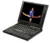
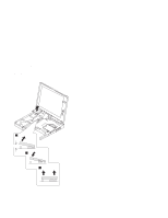
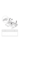
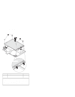
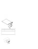
1130 System Board DIMM (If Installed) (1020) Battery Pack (1030) Hard Disk Drive (1040) Keyboard Bezel (1050) LCD Assembly (1070) Speaker (1080) HDD Flat Cable (1081) PC Card Slot Assembly (1090) Heat Sink (1100) CPU Mini Cartridge (1110) Fan (1120) Apply grease (0.2 grams) over the module. Refer to step 5 on page 60 for the location of the module. Notes: 1. The system unit serial number must be restored when the system board is replaced. Select the option Set system identification on the maintenance diskette. The flash ROM on the system board contains the vital product data (VPD)-that is, the system unit serial number, system board system number, and other computer-unique data. 2. Do not power off the computer when restoring the VPD. The system unit serial number label is attached to the base cover. Step Size (Quantity) Torque 2 Hex stud screw, silver hex-head (6) 4 kgcm 3 M2 x 3 mm, yellow pan-head (2) 1.5 kgcm When re-installing: Make sure you use the correct screw, and tighten all screws firmly to the torque shown in the table if you have a torque screwdriver. Never use a screw that you removed. Use a new one. Make sure the screws are tightened firmly (see "Screw Tightening Information" on page 4 if you do not have a torque screwdriver). 62
-
 1
1 -
2
-
3
-
4
-
5
-
6
-
7
-
8
-
9
-
10
-
11
-
12
-
13
-
14
-
15
-
16
-
17
-
18
-
19
-
20
-
21
-
22
-
23
-
24
-
25
-
26
-
27
-
28
-
29
-
30
-
31
-
32
-
33
-
34
-
35
-
36
-
37
-
38
-
39
-
40
-
41
-
42
-
43
-
44
-
45
-
46
-
47
-
48
-
49
-
50
-
51
-
52
-
53
-
54
-
55
-
56
-
57
-
58
-
 59
59 -
 60
60 -
 61
61 -
 62
62 -
 63
63 -
 64
64 -
 65
65 -
 66
66 -
 67
67 -
 68
68 -
 69
69 -
70
-
71
-
72
-
73
-
74
-
75
-
76
-
77
-
78
-
79
-
80
-
81
-
82
-
83
-
84
-
85
-
86
-
87
-
88
 |
 |