IBM IC25N020ATDA04 Hard Drive Specifications - Page 126
Option Bit. This indicates that the Option Bit of the Sector Count Register be specified.
 |
View all IBM IC25N020ATDA04 manuals
Add to My Manuals
Save this manual to your list of manuals |
Page 126 highlights
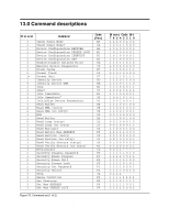
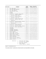
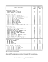
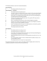
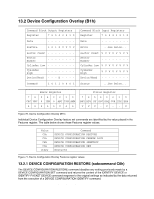
The following symbols are used in the command descriptions: Output Registers 0 This indicates that the bit must be set to 0. Output Registers - continued 1 This indicates that the bit must be set to 1. D The device number bit. Indicates that the device number bit of the Device/Head Register should be specified. Zero selects the master device and one selects the slave device. H Head number. This indicates that the head number part of the Device/Head Register is an output parameter and should be specified. L LBA mode. This indicates the addressing mode. Zero specifies CHS mode and one specifies LBA addressing mode. R Retry. This indicates that the Retry bit of the Command Register be specified. B Option Bit. This indicates that the Option Bit of the Sector Count Register be specified. (This bit is used by Set Max ADDRESS command.) V Valid. This indicates that the bit is part of an output parameter and should be specified. x This indicates that the hex character is not used. - This indicates that the bit is not used. Input Registers 0 This indicates that the bit is always set to 0. 1 This indicates that the bit is always set to 1. H Head number. This indicates that the head number part of the Device/Head Register is an input parameter and will be set by the device. V Valid. This indicates that the bit is part of an input parameter and will be set to 0 or 1 by the device. N Not recommendable condition for start up. Indicates that the condition of device is not recommendable for start up. - This indicates that the bit is not part of an input parameter. The command descriptions show the contents of the Status and Error Registers after the device has completed processing the command and has interrupted the host. Travelstar 48GH, 30GN & 15GN hard disk drive specifications 112
-
 1
1 -
2
-
3
-
4
-
5
-
6
-
7
-
8
-
9
-
10
-
11
-
12
-
13
-
14
-
15
-
16
-
17
-
18
-
19
-
20
-
21
-
22
-
23
-
24
-
25
-
26
-
27
-
28
-
29
-
30
-
31
-
32
-
33
-
34
-
35
-
36
-
37
-
38
-
39
-
40
-
41
-
42
-
43
-
44
-
45
-
46
-
47
-
48
-
49
-
50
-
51
-
52
-
53
-
54
-
55
-
56
-
57
-
58
-
59
-
60
-
61
-
62
-
63
-
64
-
65
-
66
-
67
-
68
-
69
-
70
-
71
-
72
-
73
-
74
-
75
-
76
-
77
-
78
-
79
-
80
-
81
-
82
-
83
-
84
-
85
-
86
-
87
-
88
-
89
-
90
-
91
-
92
-
93
-
94
-
95
-
96
-
97
-
98
-
99
-
100
-
101
-
102
-
103
-
104
-
105
-
106
-
107
-
108
-
109
-
110
-
111
-
112
-
113
-
114
-
115
-
116
-
117
-
118
-
119
-
120
-
 121
121 -
 122
122 -
 123
123 -
 124
124 -
 125
125 -
 126
126 -
 127
127 -
 128
128 -
 129
129 -
 130
130 -
 131
131 -
132
-
133
-
134
-
135
-
136
-
137
-
138
-
139
-
140
-
141
-
142
-
143
-
144
-
145
-
146
-
147
-
148
-
149
-
150
-
151
-
152
-
153
-
154
-
155
-
156
-
157
-
158
-
159
-
160
-
161
-
162
-
163
-
164
-
165
-
166
-
167
-
168
-
169
-
170
-
171
-
172
-
173
-
174
-
175
-
176
-
177
-
178
-
179
-
180
-
181
-
182
-
183
-
184
-
185
-
186
-
187
-
188
-
189
-
190
-
191
-
192
-
193
-
194
-
195
-
196
-
197
-
198
-
199
-
200
-
201
-
202
-
203
-
204
-
205
-
206
-
207
-
208
-
209
-
210
-
211
-
212
-
213
-
214
-
215
-
216
-
217
-
218
-
219
-
220
 |
 |