Icom IC-R8500 Instruction Manual
Icom IC-R8500 Manual
 |
View all Icom IC-R8500 manuals
Add to My Manuals
Save this manual to your list of manuals |
Icom IC-R8500 manual content summary:
- Icom IC-R8500 | Instruction Manual - Page 1
INSTRUCTION MANUAL COMMUNICATIONS RECEIVER iC- r8500 - Icom IC-R8500 | Instruction Manual - Page 2
IMPORTANT READ THIS INSTRUCTION MANUAL CAREFULLY before attempting to operate the receiver. SAVE THIS INSTRUCTION MANUAL. This instruction manual contains important safety and operating instructions for the IC-R8500. EXPLICIT DEFINITIONS WORD DEFINITION RWARNING Personal injury, fire shock may - Icom IC-R8500 | Instruction Manual - Page 3
14 s Data communications 16 5 MEMORY CHANNELS 17- 22 s General 17 s Bank selection 17 s Channel selection 18 s Programming 19 s Copy and paste (memory editing 19 s Clearing 19 s Channel/bank names 20 s Assigning channels numbers 21 6 SCANS 23- 28 s Operation 23 s Mode select function 25 - Icom IC-R8500 | Instruction Manual - Page 4
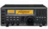
1 PANEL DESCRIPTION s Front panel @0 q POWER w SLEEP/ SET S 1 3 5 7 9 +20dB +60dB SIGNAL iC- r8500 COMMUNICATION RECEIVER FM SLEEP LOCK NB AFC AGC-F APF-N RECV 10-ATT-20 BANK ICOM I REC REMOTE MODE e WFM FM AM SSB/CW TS REC OUT r NB/AFC AGC 10dB 20dB TS PHONES AF GAIN - Icom IC-R8500 | Instruction Manual - Page 5
IC-R8500 M 1 QZ 4 GHI 2 ABC 5 JKL 3 DEF 6 MNO . ; , M-CH BANK 7 PRS . 8 TUV 0 9 WXY CE NAME BANK ENT ENT MEMO SEL PROG AUTO SCAN/ SCAN APF] control to adjust the center of the audio !7 MAIN DIAL Changes the operating frequency, set mode contents, strength of the received signal. ¯ Shows - Icom IC-R8500 | Instruction Manual - Page 6
1 PANEL DESCRIPTION POWER SLEEP/ SET REC REMOTE REC OUT PHONES S 1 3 5 7 9 +20dB +60dB SIGNAL iC- r8500 COMMUNICATION RECEIVER FM SLEEP LOCK NB AFC AGC-F APF-N RECV 10-ATT-20 BANK ICOM WFM MODE FM AM SSB/CW NB/AFC AF GAIN AGC 10dB 20dB SQUELCH APC IF SHIFT TS TS SPCH LOCK APF @1 - Icom IC-R8500 | Instruction Manual - Page 7
1 PANEL DESCRIPTION ∞ OFF DLY kHz SEL-CH SKIP-CH IC-R8500 M 1 QZ 2 ABC 3 DEF . ; , M-CH 4 GHI 5 JKL 6 MNO BANK @8 7 PRS 8 TUV 9 WXY BANK ENT . 0 CE ENT NAME MEMO PROG AUTO PRIO SCAN/ SCAN SET @7 SEL SKIP VSC DLY D/S M-CH DELAY/SPEED M-SET BANK M-CL MW @1 @2 @3 @4 - Icom IC-R8500 | Instruction Manual - Page 8
(p. 10) Connects an RS-232C cable. An RS-232C cable can be used to connect the IC-R8500 to a PC. In this way commands can be sent to the receiver via the PC. w CI-V REMOTE CONTROL JACK (p. 10) Allows connection to an Icom CI-V system transceiver or another receiver for the transceive function. Also - Icom IC-R8500 | Instruction Manual - Page 9
q REMOTE INDICATOR (p. 35) Appears when a level control command is received from a PC via CI-V data. • When this indicator appears, the control knob's setting is ignored. • This indicator will disappear when the control knob is rotated. w MODE INDICATORS (p. 13) Show the operating mode. e FREQUENCY - Icom IC-R8500 | Instruction Manual - Page 10
temperature over the useable temperature range. Specifications are not guaranteed under such conditions. D Receiver stand The base of the IC-R8500 has an adjustable stand for desktop use. Set the stand to one of two angles depending on your operating conditions. D Optional bracket and carrying - Icom IC-R8500 | Instruction Manual - Page 11
2 CONNECTIONS s Required connections IC-R8500 External speaker (p. 44) Connect either power source Supplied DC power cable Unplug the jumper plug from the [DC13.8V] jack. AC adapter AD-55/A/V Computer control (p. 10) TV adapter or high speed data connection (pgs. 16, 40) The jumper plug must - Icom IC-R8500 | Instruction Manual - Page 12
receiver operation. Connecting a poor quality antenna to the IC-R8500 will result in less than optimum performance. The IC-R8500 / SET ] momentarily to exit quick set mode. 500 HF ANT s Grounding RWARNING: NEVER aligning the center conductor pin on the cable. Tighten the nut onto the plug body - Icom IC-R8500 | Instruction Manual - Page 13
in initial set mode (p. 32). s Connecting to a PC The IC-R8500 can connect directly to a personal computer providing control of multiple functions such as instant frequency/name programming using appropriate software. See pgs. 35, 36 for the control command table. RS-232C cable Personal computer - Icom IC-R8500 | Instruction Manual - Page 14
3 FREQUENCY SETTING s Read me first The IC-R8500 uses memory channels for storage of frequencies (as well as mode, tuning steps, etc.). When turning power OFF or changing memory channels, the previously displayed frequency cannot be recalled unless it has been stored into a memory channel. Therefore - Icom IC-R8500 | Instruction Manual - Page 15
between the range of 0.5-199 SCAN SET DLY LOCK kHz *ICOM IC-R8500 function is activated. mode. Rotate the [M-CH] selector to select the "LOCK" indication. Ž Rotate the main dial to set the lock function coverage to "DIAL" or "PANEL." Push [SLEEP SET ] momentarily to exit quick set mode - Icom IC-R8500 | Instruction Manual - Page 16
power ON, check the display for indications below and remove as follows: Push [SLEEP] Push and hold [SPCH • LOCK] Push [NB/AFC] FM SLEEP LOCK NB AFC AGC-F APF-N RECV 10-ATT-20 BANK *ICOM ∞ OFF DLY kHz IC-R8500 Push [AGC] Push [10dB] and/or [20 dB] s Mode selection Push one of the mode - Icom IC-R8500 | Instruction Manual - Page 17
have a wide bandwidth which makes them easy to receive. However, you may be tuned off-center resulting in audio distortion. The IC-R8500's offcenter indicators appear in such cases, making it easy to fine tune to the center of the frequency. D AFC AFC stands for automatic frequency control. The AFC - Icom IC-R8500 | Instruction Manual - Page 18
audio. The APF can be used for adjusting the audio response. The IC-R8500 has two selectable width filters.* Use the appropriate filter width for optimum receiving. Œ Push the [APF] switch. Rotate the [APF] control to adjust the peak fre- quency. Ž To change the filter width*, push [APF] for 1 sec - Icom IC-R8500 | Instruction Manual - Page 19
output 200 mVrms/4.7 kΩ SCAN SET AF IN to [REC OUT] 2-conductor 3.5(d) plugs to [REC REMOTE] SQUELCH IN TU or TNC Personal computer D Receiving method Œ Connect a terminal unit as above. Select FM mode (or USB, CW modes for HF band data communications). Ž Set the receiver to the desired - Icom IC-R8500 | Instruction Manual - Page 20
appears. The table below gives a general overview of the IC-R8500's memory channels. BANK INITIAL CONTENTS USAGE 40 memories × 20 banks For normal use. Frequency, mode, tuning step, name and ATT information can be programmed. The number of channels in each bank is user-assignable. Banks cannot - Icom IC-R8500 | Instruction Manual - Page 21
. Banks can be selected with the [BANKv]/[BANKw] keys only. [BANK ] [BANK ] [M-CH] selector Convenient: Automatic bank limit When starting memory scan, the bank limit function is activated automatically. This automatic selection can be deactivated. See p. 26. D Using the keypad Memory channels in - Icom IC-R8500 | Instruction Manual - Page 22
the keypad. • When the memory channel is blank, use keypad entry only to set the frequency. Ž Set operating mode (p. 13) and tuning steps (p. 12). Push and hold [MW] until the receiver emits 3 beeps. • The information is stored in the memory channel. NOTE: When changing the memory channel before - Icom IC-R8500 | Instruction Manual - Page 23
can be easily copied to other channels using the copy/paste function. D Channel name programming Œ Select the desired memory channel. Set the frequency (and mode/tuning steps), then push and hold the [MW] key. • When no data is programmed, "BLANK" appears and memory names cannot be programmed - Icom IC-R8500 | Instruction Manual - Page 24
s Assigning channel numbers The IC-R8500 has 20 banks in which memory channels can be programmed and arranged. By default, each bank contains 40 memory channels, however, channels can be deleted from or added (inserted) to banks to suit your preferences and operating style. Deleted channels - Icom IC-R8500 | Instruction Manual - Page 25
bank. ADD.10CH 10 channels will be added 'at the end' of the selected bank. Push [BANK] for 1 sec. to perform the selected operation. • The memory channel(s) are deleted from the "FREE" bank and added/inserted to the selected bank. • Memory channels cannot be added/inserted into a memory - Icom IC-R8500 | Instruction Manual - Page 26
6 SCANS s Operation D Memory scan All memory channels (except skip channels) in the selected bank are scanned at up to 40 ch/sec. Œ Push [M-CH • BANKv] or [ENT • BANKw] to select the desired bank. • Direct selection is also available as below. Set the [SQUELCH] control to the threshold point. Ž - Icom IC-R8500 | Instruction Manual - Page 27
mode and tuning steps. Refer to p. 27 for details. Start/stop: Œ Set the [SQUELCH] control to the threshold point. Push [PROG] to start the scan. • "PROG" (and scan range number write scan operates in the same way as programmed scan. However, when a signal is received, the received frequency is - Icom IC-R8500 | Instruction Manual - Page 28
the setting ON and OFF. • SKIP-CH appears when 'skip' is set. ICOM SKIP-CH IC-R8500 The channel is specified as a 'skip' channel. • Programming skip frequencies (for programmed scan) Œ Start programmed scan. When the scan pauses on an undesired signal, push [MW] for 1 sec. • The frequency is - Icom IC-R8500 | Instruction Manual - Page 29
activates for any scan. • The VSC function resumes the scan on unmod- ∞ ulated signals even when the resume condition is set to "OFF" or " ". VSC appears FM ∞ VSC OFF DLY kHz ICOM- IC-R8500 Unmodulated signal Scan edge 1 Modulated signal Scan edge 2 Scan Skip Scan pauses or is cancelled - Icom IC-R8500 | Instruction Manual - Page 30
sec. after that. Signal no signal receiving a signal no signal Scan scanning pausing scanning 3 sec. Signal no signal receiving a signal no signal Scan pausing scanning delay time scanning • Scan cancel Scan is cancelled when a signal is found during scan. ∞ OFF DLY 27 Signal no signal - Icom IC-R8500 | Instruction Manual - Page 31
dial Adjustable via the [M-CH] selector VR:DLY SPD=MAX Scan delay is assigned to the [DELAY/SPEED] control D Scan speed When scan speed is assigned to the [DELAY/SPEED] control (see above), the scan speed can be instantly updated during scan operation. The name area shows as at right for 1 sec - Icom IC-R8500 | Instruction Manual - Page 32
than once, otherwise the sleep period may be changed. To turn ON the receiver after the sleep timer has turned power OFF, push [POWER] OFF then ON again. • The sleep timer is cancelled. after 2 sec. SLEEP kHz ICOM IC-R8500 Previous display Push SLEEP/ SET once SLEEP Set time Minutes 29 - Icom IC-R8500 | Instruction Manual - Page 33
values or conditions of functions. The IC-R8500 has 2 separate set modes: quick set mode and initial set mode. D Selecting quick set mode Œ Push [SLEEP/ SET ] for 1 sec. • Quick set mode is selected and one of its items appears. Rotate the [M-CH] control to select the desired item. Ž Rotate - Icom IC-R8500 | Instruction Manual - Page 34
. This announcement can be turned ON and OFF. ON The REC REMOTE jack can be used (default). OFF The REC REMOTE jack has no function and no relay switching sound is heard. ON The detected frequency is announced when scan pauses (default). OFF The optional voice synthesizer activates via the [SPCH - Icom IC-R8500 | Instruction Manual - Page 35
automatically set according to the connected controller or other Icom CI-V radio. CIV TRAN Transceive operation is possible with the IC-R8500 connected to an Icom CI-V radio. When "ON" is selected, changing the frequency, operating mode, etc. on the IC-R8500 automatically changes those of connected - Icom IC-R8500 | Instruction Manual - Page 36
be connected to pins 4 and 5 (RTS/CTS) via the internal circuit board ('coffee beans'). Outer Pin Inner Outer Port name REMOTE GND Description Input/output port for from an antenna connector in WFM mode) Grounded. D AGC OUT jack level: 200 mV rms (at Mod.=1 kHz, Dev.=3.5 kHz) Output impedance - Icom IC-R8500 | Instruction Manual - Page 37
connection to the AD-55A/V only Grounded. Outer [POWER] switch Receiver circuit Internal regulator circuit • DC 13.8 V Pin REMOTE jack Outer Inner 3.5 mm (diam.) 2-conductor Pin Inner Outer Port name SQL GND Description • Grounded when squelch opens. • Can be deactivated via initial set mode - Icom IC-R8500 | Instruction Manual - Page 38
10 CONTROL COMMANDS The IC-R8500 can be connected to a PC via the PC's RS-232C port. This allows you to control the receiver s Command table Operation Cn Sc Remark Reading freq. edges Reading operating freq. Reading operating mode 02 - 03 - 04 - Reading M-ch contents package Reading bank - Icom IC-R8500 | Instruction Manual - Page 39
of programming the following into memory channel 123 of bank number 19: • Frequency: 1,234,567,890 Hz • Mode: FM • Tuning step: 199.5 kHz (programmable step) • Attenuator: 10 dB • Scan select: specified • Scan skip: specified • Memory name: IC-R8500 • Clearing the specified channel data (Memory channel - Icom IC-R8500 | Instruction Manual - Page 40
125 V 3 A) s Level adjustments R254 R252 s CPU resetting If the IC-R8500 is behaving erratically, this may be an indication of a CPU malfunction. In such cases, reset the CPU. While pushing [MW], push [POWER] in to turn on the receiver power. • The CPU is reset. NOTE: Resetting the CPU clears all - Icom IC-R8500 | Instruction Manual - Page 41
) when pushing [SPCH] or when a signal is detected during scan (see p. 31, 32 for settings). ΠRemove the top cover as shown opposite. IC-R8500 has a CW narrow mode which provides better S/N (signal-to-noise) and also rejects nearby interference. The CW narrow filter is helpful when receiving - Icom IC-R8500 | Instruction Manual - Page 42
crystal with a stability of ± 3 ppm is built-in to the receiver. For more demanding operation, the CR-293 HIGH STABILITY CRYSTAL UNIT is available. It has a stability above is guaranteed 1 min. after power ON. Ground spring 39 Metal plate Shield cover PLL unit CR-293 Internal crystal unit - Icom IC-R8500 | Instruction Manual - Page 43
[IF OUT] red from [IF IN] [AGC] black from [TV CONTROL] stereo headphones TV-R7100 D Operation Œ Turn on the TV-R7100, IC-R8500 and all connected equipment. Select WFM mode. Ž ¯ Push OUT [FM/TV] on the TV-R7100 to select "TV" when receiving TV broadcasts or ATV. ¯ Push IN [FM/TV] on the TV - Icom IC-R8500 | Instruction Manual - Page 44
this chart, contact your nearest Icom Dealer or Service Center. POWER RECEIVE FUNCTIONS PROBLEM POSSIBLE CAUSE SOLUTION REF. Power does not turn ON when [POWER] is pushed in. • DC power cable is improperly connected. • A fuse is blown. • During AC adapter operation, the jumper connector is - Icom IC-R8500 | Instruction Manual - Page 45
TROUBLESHOOTING 13 PROBLEM . No scan will function scan into the selected scanning group. scan edge channels or select a different does not function. programmed scan group. Memory scan does not function. Select memory scan scan does not function. have been programmed. auto write bank. Scan - Icom IC-R8500 | Instruction Manual - Page 46
14 SPECIFICATIONS s General • Frequency coverage • Mode • Number of memory channels • Antenna connector • Usable temperature range • Frequency stability • Power supply requirement • Current drain (at 13.8 V DC) • Dimensions (projections not included) • Weight • Intermediate frequencies s Receiver • - Icom IC-R8500 | Instruction Manual - Page 47
Carrying handle, convenient for portable operation. Use the screws supplied with the IC-R8500; DO NOT use the screws supplied with the MB-23. CT-17 CI-V LEVEL CONVERTER Receiver mounting bracket for mobile operation. AD-55/A/V AC ADAPTER For remote control of up to 4 receivers from 1 PC. You can - Icom IC-R8500 | Instruction Manual - Page 48
Count on us! A-5395Y-1EX-Œ Printed in Japan Copyright © 1996 by Icom Inc. 1-1-32 Kamiminami, Hirano-ku, Osaka 547-0003 Japan
-
 1
1 -
 2
2 -
 3
3 -
 4
4 -
 5
5 -
 6
6 -
 7
7 -
8
-
9
-
10
-
11
-
12
-
13
-
14
-
15
-
16
-
17
-
18
-
19
-
20
-
21
-
22
-
23
-
24
-
25
-
26
-
27
-
28
-
29
-
30
-
31
-
32
-
33
-
34
-
35
-
36
-
37
-
38
-
39
-
40
-
41
-
42
-
43
-
44
-
45
-
46
-
47
-
48
 |
 |

INSTRUCTION MANUAL
iC- r8500
COMMUNICATIONS RECEIVER