Icom ID-51A Service Manual
Icom ID-51A Manual
 |
View all Icom ID-51A manuals
Add to My Manuals
Save this manual to your list of manuals |
Icom ID-51A manual content summary:
- Icom ID-51A | Service Manual - Page 1
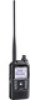
VHF/UHF TRANSCEIVER S-14914XZ-C1 March 2013 - Icom ID-51A | Service Manual - Page 2
RF signal of more than 20 dBm (100 mW) to the antenna connector. This could damage the transceiver's front-end. (ID-51A) ORDERING PARTS Be sure to include the following four points when ordering replacement parts: 1. 10-digit Icom part number 2. Component name 3. Equipment model name and unit name - Icom ID-51A | Service Manual - Page 3
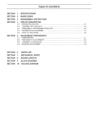
SECTION SECTION SECTION 1 SPECIFICATIONS 2 INSIDE VIEWS 3 DISASSEMBLY INSTRUCTION 4 CIRCUIT DESCRIPITON 4-1 RECEIVER CIRCUITS 4-1 4-2 TRANSMITTER CIRCUITS TRANSMIT ADJUSTMENT 5-3 5-4 RECEIVE ADJUSTMENT 5-11 SECTION 6 PARTS LIST SECTION 7 MECHANICAL PARTS SECTION 8 BOARD LAYOUTS SECTION 9 BLOCK - Icom ID-51A | Service Manual - Page 4
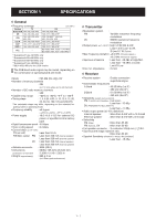
174*4, 380-479*2 ALL - BC Radio (AM): 0.520-1.710 MHz BC Radio (FM): 76.0-108.0 MHz*5 16.0 V DC for external DC power, or specified Icom's battery pack • Digital transmission speed : 4.8 kbps • Voice than 450 mA (Internal speaker) • Antenna connector • Dimensions (projections not included) - Icom ID-51A | Service Manual - Page 5
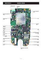
SECTION 2. INSIDE VIEWS • LOGIC UNIT EEPROM (IC3) DSP FLASH MEMORY (IC20) MIC MUTE SW (IC16) LEVEL CONVERTER (IC21) DSP MODE SW (IC390) AF FILTER (IC350) AF AMP (IC2) AF AMP (IC300) TONE FILTER (Q330) TONE FILTER (Q370) 3VS LINE REGULATOR (IC12) MIC SW (Q21) PTT SW (Q20) CHARGING CONTROLLER ( - Icom ID-51A | Service Manual - Page 6
• MAIN UNIT (TOP VIEW) CURRENT DETECTOR (IC5) ATT (Q907) ATT (Q906) RF AMP (Q780) D/A CONVERTER (IC952) LOCK VOLTAGE BUFFER (Q451) PLL IC (Band B) (IC450) +4 V REGULATOR (IC3) REFERENCE FREQUENCY OSCILLATOR (X1) DISCRIMINATOR (Band B) (X900) 2ND IF FILTER (Band B) (For FM and AM modes) (FI900) AM - Icom ID-51A | Service Manual - Page 7
DRIVE AMP (Q41) • MAIN UNIT (BOTTOM VIEW) 1ST IF FILTER (Band A) (FI3) CHARGING CONTROLLER (IC8) PS3 LINE REGULATOR (IC13) +3.3 V REGULATOR (IC11) RADIO AUDIO BUFFER (IC955) RADIO IC (IC441) AF AMP (IC2) VHF RF AMP (Band A/B) (Q702) UHF RF AMP (Band A/B) (Q602) VHF RF AMP (Band A) (Q701) UHF RF - Icom ID-51A | Service Manual - Page 8
SECTION 3. DISASSEMBLY INSTRUCTION 1. REMOVING THE LOGIC UNIT 1) Remove 2 dials and antenna nut from the front panel. Inner dial Antenna nut Remove with; "ICOM Driver (Q)" (8960000370) Outer dial 4) Remove 6 screws from the LOGIC UNIT. 5) Unsolder 6 points at the rotary encoder. Screws x5 - Icom ID-51A | Service Manual - Page 9
2. REMOVING THE MAIN UNIT 1) Unsolder 2 points on the shield plate. UNSOLDER Solder remover 3) Unsolder a point at the antenna connector. UNSOLDER Solder remover Shield plate 2) Remove 5 screws from the shield plate, and then remove it. 4) Remove 6 screws from the MAIN UNIT, and then remove - Icom ID-51A | Service Manual - Page 10
RF CIRCUITS VHF BAND (108-174 MHz) The RF signal from the antenna is passed through two LPFs (L513, L515, L516, C547, C549, C553 D742, L740, C741 to C743). UHF BAND (380-479 MHz) The RF signal from the antenna is passed through the HPF (L512, L514, C545, C548, C550, C551 and C554), two LPFs - Icom ID-51A | Service Manual - Page 11
1ST IF CIRCUITS VHF BAND (108-174 MHz) • Band A (137-174 MHz) The RX signal from the RF circuit is applied to the 1st mixer (Q820) and mixed with the 1st LO signal, resulting in the 46.35 MHz 1st IF signal. The converted signal is passed through the RF SW (D820), 1st IF filter (FI3) and limiter (D23 - Icom ID-51A | Service Manual - Page 12
2ND IF CIRCUITS • Band A The 1st IF signal from the 1st IF circuit is applied to the IF IC (IC13, pin 16), which contains the 2nd IF AMP, 2nd mixer, FM demodulator, and so on. The 1st IF signal is mixed with the 45.9 MHz 2nd LO signal, resulting in the 450 kHz 2nd IF signal. The converted signal is - Icom ID-51A | Service Manual - Page 13
9 and 8, 5 and 7), and then applied to the D/A converter (MAIN UNIT: IC11, pin 18) to be adjusted in volume level. RADIO RECEIVE CIRCUITS • FM BAND (76-108 MHz) The RF signal from the antenna or earphone is passed through two LPFs (L513, L515, L516, C547, C549, C553, C555 and C556), ANT SW (D506 - Icom ID-51A | Service Manual - Page 14
4-2 TRANSMIT CIRCUITS TX AF CIRCUIT (LOGIC UNIT) The AF signal from the internal or external microphone (MIC signal) is applied to the audio processor LSI (IC25), through the ATT (R190 and R198). The audio processor LSI contains 16-bit liner CODEC, MIC AMP, audio filters, D/A converter, and so on. • - Icom ID-51A | Service Manual - Page 15
, C547, C549, C553, C555 and C556), before being applied to the antenna. • While operating on the UHF band The amplified TX signal is passed (L512, L514, C545, C548, C550, C551 and C554), before being applied to the antenna. APC CIRCUITS (MAIN UNIT) The voltage produced at the LPFs (VHF band; L513, - Icom ID-51A | Service Manual - Page 16
4-3 FREQUENCY SYNTHESIZER CIRCUIT (MAIN UNIT) VCOs The ID-51A/E has total of four VCOs; two VCOs for band A and another two for band B. • Band A VHF VCO (VCO1 UNIT) The VHF VCO (Q311, D304-D306) - Icom ID-51A | Service Manual - Page 17
and au- O dio IC. D12 KR2 Key matrix return. I Battery type detection. D13 BTDET L=An appropriate battery pack is I attached. D14 PWRSW [POWER] key input. L=Pushed. I D15 SCLK_R Radio IC serial clock. O D2 G_RXD UART data from the internal GPS module. I D4 BTONE WX alert signal - Icom ID-51A | Service Manual - Page 18
circuit power control. M7 AR3C (Band A) O L=While receiving on band A. M8 LCDRS LCD driver serial data. O M9 LCDCS LCD driver chip select. O N1 CLIN CI-V/CLONE UART (300-38400 bps) data. I GPS module operating mode N12 G_HIB (Normal/Sleep) switching control. O L=While in the sleep mode - Icom ID-51A | Service Manual - Page 19
connector FM Attenuator deviation meter 40 dB DO NOT transmit while an SSG is connected to the antenna connector. RF power meter 0.1-6 W/50 Ω POWER SUPPLY CONNECTION Frequency counter • Adjustment at 13.5 V • Adjustment at 5.5 V or 7.4 V To the [DC IN] jack OPC-254L Black: Be - Icom ID-51A | Service Manual - Page 20
• ENTERING THE ADJUSTMENT MODE 1) Connect the JIG cable "#1" to [SP]. (See page 5-1) 2) While holding down [SQL] and , turn ON the power. [SQL] Push to turn ON the power. Connect the JIG cable "#1" (See page 5-1) here. [QUICK/MENU] • KEY ASSIGNMENTS FOR THE ADJUSTMENT MODE Adjusts the value for - Icom ID-51A | Service Manual - Page 21
ITEM OPERATION DRIVE AMP IDLING CURRENT (At 5.5 V) [ID5] 1 1) Set the power supply voltage to 5.5 V. 2) Connect an RF power meter to the antenna connector. 3) Connect an ammeter between the power supply and transceiver. 4) Set the item [IP5] to "00." VHF UHF 2 • While transmitting, adjust the - Icom ID-51A | Service Manual - Page 22
Low power) 11 FINAL AMP IDLING CURRENT (At 7.4 V) 1 1) Set the power supply voltage to 7.4 V. 2) Connect an RF power meter to the antenna connector. 3) Connect an ammeter between the power supply and transceiver. VHF (Hi power) 2 • While transmitting, adjust the idling current using [DIAL], and - Icom ID-51A | Service Manual - Page 23
AMP IDLING CURRENT (At 13.5 V) 1 1) Set the power supply voltage to 13.5 V. (supplying from [DC IN]) 2) Connect an RF power meter to the antenna connector. 3) Connect an ammeter between the power supply and transceiver. 4) Set the item [IP1] to "00." VHF (Hi power) 2 • While transmitting, adjust - Icom ID-51A | Service Manual - Page 24
OPERATION TRANSMIT POWER -VHF(BAND LOW) (BAND HIGH) [PO5] 1 1) Set the power supply voltage to 5.5 V. 2) Connect an RF power meter to the antenna connector. 2 3) While transmitting, adjust the TX power using [DIAL], and then push to store the adjustment value. 3 -UHF- 4 (BAND LOW) (BAND HIGH - Icom ID-51A | Service Manual - Page 25
ITEM OPERATION TRANSMIT POWER - 1 1) Set the power supply voltage to 13.5 V. (supplying from [DC IN]) 2) Connect an RF power meter to the antenna connector. -VHF(Hi power) [BAND LOW] 2 • While transmitting, adjust the TX power using [DIAL], and then push to store the adjustment value. [BAND - Icom ID-51A | Service Manual - Page 26
[FM-N (BAND LOW)] [FM (BAND HIGH)] - [MFL] [MNL] [MFH] 1 1) Set the power supply voltage to 7.4 V. 2) Connect a modulation analyzer to the antenna connector through an attenuator, and set it as; HPF : OFF LPF : 20 kHz De-emphasis : OFF Detector : (P-P)/2 3) Connect an audio generator to - Icom ID-51A | Service Manual - Page 27
ADJUSTMENT ITEM OPERATION DV BALANCE -VHF[BAND LOW] [BAND CENTER] 1 1) Set the power supply voltage to 7.4 V. 2) Connect a modulation analyzer to the antenna connector through an attenuator, and then set it as; - HPF : OFF LPF : 20 kHz De-emphasis : OFF Detector : (P-P)/2 3) No audio - Icom ID-51A | Service Manual - Page 28
[DIAL]. ADJUSTMENT ADJUSTMENT ITEM OPERATION VALUE TONE DEVIATION 1 1) Set the power supply voltage to 7.4 V. 2) Connect a modulation analyzer to the antenna connector through an attenuator, and then set it as; - HPF : OFF - LPF : 20 kHz De-emphasis : OFF Detector : (P-P)/2 3) No - Icom ID-51A | Service Manual - Page 29
Otherwise, "S-METER" and "S-METER S3 LEVEL will not be adjusted properly. 1 1) Set the power supply voltage to 7.4 V. - 2) Connect an SSG to the antenna connector and set it as; - Modulation : 1 kHz Deviation : 30% (AM) (AM S0 level) [BS0] 2 • Set the SSG as; Frequency : (Displayed on the - Icom ID-51A | Service Manual - Page 30
Otherwise, "S-METER" and "S-METER S3 LEVEL will not be adjusted properly. 1 1) Set the power supply voltage to 7.4 V. - 2) Connect an SSG to the antenna connector and set it as; - Modulation : 1 kHz Deviation : 30% (AM) (AIR S0 level) [AS0] 2 • Set the SSG as; Frequency : (Displayed on the - Icom ID-51A | Service Manual - Page 31
Level : OFF† 2 -UHFFM mode FM-N mode 3 [USQ] 4 [AIR BAND] [ASQ] 1 1) Set the power supply voltage to 7.4 V. 2) Connect an SSG to the antenna connector and set as; Frequency : (Displayed on the function display) Level : -26 dBµ (-133 dBm)† Modulation : 1 kHz Deviation : 30% (AM) [B BAND - Icom ID-51A | Service Manual - Page 32
16.7 B 17.9/16.7 B 14.2/14.1 B 14.1/9.5 T 4.6/19.1 B 11.1/9.8 T 8.9/18.0 T 9.9/14.2 B 50.9/22.9 Eqv.= This component is equivalent to the REF No. component listed above, and M.=Mounted side (T: Mounted on the Top side, B: Mounted on the Bottom side) may be substituted on parts orders and repairs - Icom ID-51A | Service Manual - Page 33
.0/16.2 T 51.0/10.7 T 51.4/9.4 T 51.8/8.1 T 53.2/10.5 T 47.6/6.9 T 45.6/9.6 T 44.4/9.1 T 43.0/7.9 Eqv.= This component is equivalent to the REF No. component listed above, and M.=Mounted side (T: Mounted on the Top side, B: Mounted on the Bottom side) may be substituted on parts orders and repairs - Icom ID-51A | Service Manual - Page 34
B 83.8/9.6 T 52.6/20.6 T 48.7/33.4 B 81.6/16.2 T 22.5/21.6 T 89.8/37.0 B 81.6/18.3 Eqv.= This component is equivalent to the REF No. component listed above, and M.=Mounted side (T: Mounted on the Top side, B: Mounted on the Bottom side) may be substituted on parts orders and repairs. S.=Surface - Icom ID-51A | Service Manual - Page 35
45.5/30.1 49.6/26.4 46.1/18.5 12.0/8.0 14.8/8.1 6.3/25.2 9.8/25.2 11.0/25.2 6.5/24.3 Eqv.= This component is equivalent to the REF No. component listed above, and M.=Mounted side (T: Mounted on the Top side, B: Mounted on the Bottom side) may be substituted on parts orders and repairs. S.=Surface - Icom ID-51A | Service Manual - Page 36
.9 T 64.1/9.0 B 73.1/15.7 B 69.0/12.0 B 68.3/13.0 T 74.9/6.6 B 75.2/16.9 B 72.2/15.7 Eqv.= This component is equivalent to the REF No. component listed above, and M.=Mounted side (T: Mounted on the Top side, B: Mounted on the Bottom side) may be substituted on parts orders and repairs. S.=Surface - Icom ID-51A | Service Manual - Page 37
21.4 B 85.7/36.6 T 60.3/15.1 T 49.3/18.6 T 13.5/10.0 T 33.5/35.3 B 81.7/33.4 Eqv.= This component is equivalent to the REF No. component listed above, and M.=Mounted side (T: Mounted on the Top side, B: Mounted on the Bottom side) may be substituted on parts orders and repairs. S.=Surface mount - Icom ID-51A | Service Manual - Page 38
T 5.4/15.4 T 6.6/16.1 T 10.2/16.0 T 4.8/12.9 T 9.3/15.0 T 12.2/10.9 T 14.0/11.8 T 14.3/14.7 Eqv.= This component is equivalent to the REF No. component listed above, and M.=Mounted side (T: Mounted on the Top side, B: Mounted on the Bottom side) may be substituted on parts orders and repairs - Icom ID-51A | Service Manual - Page 39
T 5.4/15.4 T 6.6/16.1 T 10.2/16.0 T 4.8/12.9 T 9.3/15.0 T 12.2/10.9 T 14.0/11.8 T 14.3/14.7 Eqv.= This component is equivalent to the REF No. component listed above, and M.=Mounted side (T: Mounted on the Top side, B: Mounted on the Bottom side) may be substituted on parts orders and repairs - Icom ID-51A | Service Manual - Page 40
.9 B 38.3/2.4 B 38.3/3.3 B 76.0/21.0 B 70.8/35.6 B 70.8/36.5 B 75.1/24.0 B 72.9/25.5 Eqv.= This component is equivalent to the REF No. component listed above, and M.=Mounted side (T: Mounted on the Top side, B: Mounted on the Bottom side) may be substituted on parts orders and repairs. S.=Surface - Icom ID-51A | Service Manual - Page 41
B 75.4/27.6 B 71.2/31.0 B 41.6/11.0 B 41.6/11.9 B 41.6/12.8 B 41.6/15.9 B 46.1/5.1 Eqv.= This component is equivalent to the REF No. component listed above, and M.=Mounted side (T: Mounted on the Top side, B: Mounted on the Bottom side) may be substituted on parts orders and repairs. S.=Surface - Icom ID-51A | Service Manual - Page 42
36.1 B 61.8/31.1 B 60.2/31.1 B 58.4/32.0 B 57.9/29.9 B 58.4/31.1 B 49.6/26.3 Eqv.= This component is equivalent to the REF No. component listed above, and M.=Mounted side (T: Mounted on the Top side, B: Mounted on the Bottom side) may be substituted on parts orders and repairs. S.=Surface mount - Icom ID-51A | Service Manual - Page 43
41.2 T 50.3/24.8 T 51.3/8.4 B 51.0/2.1 B 34.6/2.1 BT1 3020000390 S.LIT ML414HIV01E T 86.0/5.4 Eqv.= This component is equivalent to the REF No. component listed above, and M.=Mounted side (T: Mounted on the Top side, B: Mounted on the Bottom side) may be substituted on parts orders and repairs - Icom ID-51A | Service Manual - Page 44
EVQPQHB55 2260003300 EVQPQHB55 2260003300 EVQPQHB55 2260003300 EVQPQHB55 2250000710 F082EN7510W-1 2260003320 SKRTLAE010 2260003320 SKRTLAE010 BT1* 3020000390 ML414HIV01E [ACCESSORIES] REF NO. ORDER NO. DESCRIPTION EP1 6910018620 BLACK HANDY STRAP EP2 3310002150 FA-S270C EP3 (Optional - Icom ID-51A | Service Manual - Page 45
[ACCESSORIES] EP2 EP1 EP3 EP1(C) GPS module MP29(C) MP33(C) MP14(C) J1(C) MP1 MP39(C) EP4 MP28(C) MP22(C) MP26(C) MP44(C) MP6(C) W1(C) (Bottom view) MP24(C) MP1(C) MP49(C) S12(L) - Icom ID-51A | Service Manual - Page 46
R16 C65 R22 R58 R48 R19 SECTION 9. BOARD LAYOUTS The combination of top side and bottom side of this V45 V40 V35 V30 • LOGIC UNIT (TOP VIEW) C28 DS1 DS3 D33 DS12 J2 Q9 Q8 C90 NC NC NC NC NC NC LCDCS LCDRES LCDRS LCDCK LCDDT GND NC NC NC NC NC NC NC NC C89 R73 R72 R52 R47 R51 R49 - Icom ID-51A | Service Manual - Page 47
-V BTVIN T3C DASTB1 BTDETO BPLLSTB GND VCOMOD AUNLK ALV APLLSTB TTEMP AR3 REFMOD CLONE PCON PSC AFON INTPTT GND EXTMIC R237 R239 R242 R227 D31 R232 Q20 EP22 ARSSI ADET GND 3VS IOEN IOSTB1 AAF 5VS BRSSI BNOISE GND BDET BAF BLV DATA CK DALD R3C BR3 32K SDIO_R SCLK_R SEN_R RES_R R403 R100 Q11 R97 - Icom ID-51A | Service Manual - Page 48
BTDETO BPLLSTB GND VCOMOD AUNLK J2 ALV APLLSTB H80 TTEMP REFMOD AR3 C998 CLONE PCON PSC AFON INTPTT MICGND EXTMIC H85 C181 R167 R168 C174 C175 ANOIS ADET GND 3VS IOEN IOSTB1 AAF 5VS BRSSI BNOIS GND BDETO BAF BLV DATA CK DALD R3C BR3 32K SDIO_R SCLK_R SEN_R RES_R J3 R466 C75 C68 - Icom ID-51A | Service Manual - Page 49
J2 • MAIN UNIT (BOTTOM VIEW) J4 J5 D909 C22 C29 L6 R21 C26 IC8 C1001 R17 D906 C31 C35 MP11 EP3 R274 IC16 C360 EP788 C1000 EP787 C999 EP782 EP785 R273 C365 EP783 IC441 C446 C371 C448 C445 C34 EP23 C38 C977 C980 IC955 R462 R442 C994 C46 EP786 C447 C50 EP781 C441 C443 C979 C978 - Icom ID-51A | Service Manual - Page 50
RTC_SDA RTC_SCL RTC_IRO REALTIME CLOCK IC IC4 D16 X1 32.768kHz SQLɹ BATTERY BT1 LPF 5VS LOG3 IC13 PS3 REG PCON IC12 3VS 3VS REG CPU3V RESET IC22 CPU3 DATA,CK,DASTB1,IOSTB1 IOEN BTDET 32kHz J4 CLONE EARANT BTL4.2V VO+ AF AMP VOIC2 AFON Q20 ATT EAR BTL4.2V BUFF IC20 RADIO A B SP1 - Icom ID-51A | Service Manual - Page 51
3VS X1 15.3MHz VCOMOD VVCO3(VAV3) VCO_A 3VS,+5V IC6 AUNLK PLL IC DATA FIN CK APPS APLLSTB AVCO_SHIFT LOOP FIL VCO SHIFT Q308 D308 VHF VCO Q311,D304 VHFC UHFC LPF ANT SW D503,D504 D506,D903 D502,Q504,D511 ANT SW ANTENNA TX:400.000M~479.000MHz RX:380.000M~479.000MHz LPF LPF HPF D505, - Icom ID-51A | Service Manual - Page 52
7 6 5 EXTMIC EXTPTT VOX INTMIC MMUTE PLAY BAFMUTE BAM FMMUTE D_AS DAFS BCTCIN ACTCIN BTONE ATONE CTCOUT DTMF BAF AAF BDET ADET BR3 AR3 AUSTB CK DATA AUDI AURES EXTMIC EXTPTT VOX INTMIC MMUTE PLAY yobi3 CP54 CP06S BAFMUTE BAM FMMUTE D_AS DAFS BCTCIN ACTCIN BTONE ATONE 22P 220P C514 C513 SC_CLK - Icom ID-51A | Service Manual - Page 53
BRSSI 10 BNOISE 11 12 BDET 13 BAF 14 BLV MMZ1005Y102CT 15 DATA CK EP22 EP23 16 17 DALD 18 R3C MMZ1005Y102CT 19 BR3 BTDETO BPLLSTB VCOMOD AUNLK ALV APLLSTB TTEMP AR3 REFMOD CLONE PCON PSC AFON INTPTT EXTMIC CP06S CP50 CP06S CP38 CP06S LIST for the value and name of component. 11-2 - Icom ID-51A | Service Manual - Page 54
VSS I/O3 TC74VHC4066AFK C395 0.001 DMOD 220P C144 100k R412 C143 220P L4 3.9N MMZ1005S601CT EP13 AUSTB CK DATA AUDI MCLK R128 SC_CLK 100 SC_LR SC_SDI SC_SDO AURES 43 MODE 44 CSN 45 SCLK/SCL 46 SDATAI/SDA 47 4P BR3 AR3 *: Refer to the PARTS LIST for the value and name of component. 11-3 - Icom ID-51A | Service Manual - Page 55
AR3 BR3 ALV BLV AUNLK VCOMOD REFMOD ADET ARSSI ANOIS ASQLIN ASQLOUT BDETO BRSSI BNOIS BSQLIN BSQLOUT CK DATA IOSTB1 DASTB1 IOEN VCC-I T3C_INV TTEMP 80RF ANTSW EARANT BCIN 80MR3 5VS +5V 3VS EAR IOEN 001 C939 1 BSQLIN BNOIS BRSSI *: Refer to the PARTS LIST for the value and name of component. 11-4 - Icom ID-51A | Service Manual - Page 56
R3C R3 UHFC VHFC VBUAC VAUBC C850 47P C854 0.001 C755 AAGC BAGC 80MC 3VS 80MR3 C863 1 C864 1 Q854 DRA9114T 11-5 *: Refer to the PARTS LIST for the value and name of component. - Icom ID-51A | Service Manual - Page 57
EARANT R82 470 (Radio RF) SP1 SDRS 36 APLLSTB 35 TTEMP 34 AR3 33 REFMOD 32 CLONE 31 PCON 30 PSC 29 AFON 28 INTPTT 27 ASQLOUT BDETO BRSSI BNOIS BSQLIN BSQLOUT CK DATA CK DATA IOSTB1 IOSTB1 DASTB1 DASTB1 3VS IOEN IOEN BCC LIST for the value and name of component. 11-6 - Icom ID-51A | Service Manual - Page 58
C132 0.75P R126 120 15P C85 0.001 R89 2.2k LQW18AN8N2D00 LQW18AN8N2D00 R114 L3 4.7k C2 0.01 R3 C3 0.001 *: Refer to the PARTS LIST for the value and name of component. • VCO2 UNIT PLLOUT VCOMOD ULV VLV J1 1 2 3 4 5 6 7 8 9 10 11 12 LOOUT VCO_SHIFT UVCO3 VVCO3 C85 0.001 - Icom ID-51A | Service Manual - Page 59
) 454-1509 URL : http://www.icomamerica.com E-mail : [email protected] Phone : +1 (425) 454-7619 Glenwood Centre #150- 02) 2559 1899 Fax : +886 (02) 2559 1874 URL : http://www.asia-icom.com E-mail : [email protected] 81-850 Sopot, ul. 3 Maja 54, Poland Phone : +48 (58) - Icom ID-51A | Service Manual - Page 60
1-1-32, Kamiminami, Hirano-ku, Osaka 547-0003, Japan S-14914XZ-C1 © 2013 Icom Inc.
-
 1
1 -
 2
2 -
 3
3 -
 4
4 -
 5
5 -
 6
6 -
 7
7 -
8
-
9
-
10
-
11
-
12
-
13
-
14
-
15
-
16
-
17
-
18
-
19
-
20
-
21
-
22
-
23
-
24
-
25
-
26
-
27
-
28
-
29
-
30
-
31
-
32
-
33
-
34
-
35
-
36
-
37
-
38
-
39
-
40
-
41
-
42
-
43
-
44
-
45
-
46
-
47
-
48
-
49
-
50
-
51
-
52
-
53
-
54
-
55
-
56
-
57
-
58
-
59
-
60
 |
 |

S-14914XZ-C1
March 2013
VHF/UHF TRANSCEIVER