Icom VE-PG3 Perparation
Icom VE-PG3 Manual
 |
View all Icom VE-PG3 manuals
Add to My Manuals
Save this manual to your list of manuals |
Icom VE-PG3 manual content summary:
- Icom VE-PG3 | Perparation - Page 1
RoIP GATEWAY PREPARATION Read the "PRECAUTIONS" leaflet first, if you have not done so. Thank you for purchasing the VE-PG3. The VE-PG3 is a network converter that allows you to connect Icom radios or repeaters to a VoIP network. This guide describes the basic settings to operate the VEPG3. READ ALL - Icom VE-PG3 | Perparation - Page 2
PG3, set the transceiver and repeater as shown in the following table. • The transceiver settings affect the audio quality. • See the transceiver's instruction manual PG3. IC-FR5000/IC-FR6000 PG3 PG3 Transceivers Difference in height: More than 1m; 3.3 ft Antenna Transceiver VE-PG3 VE-PG3
-
 1
1 -
 2
2
 |
 |
M
AC adaptor ………… 1
M
Cushion sheet ………………… 1
M
Ferrite EMI filter …… 1
M
Spare connectors ………… 24
M
CD (UTILITY DISC)
Guides:
M
Precaution leaflet
M
Preparation leaflet (this guide)
M
Installation 1 leaflet
M
Installation 2 leaflet
Step 1
Required items
Accessories
About the CD (UTILITY DISC)
Options
(As of December 2012)
Other items
(As of December 2012)
M
PC
M
LAN cable
M
Ground cable
M
HUB*
2
M
Icom transceiver*
3
and their instruction manual.
M
SIP phone (KX-UT123/KX-UT136 series (Manufacture: Panasonic))*
4
*
2
The VE-PG3 can be directly connected to the PC using the MDI-X (crossover) type Ethernet cable.
*
3
See the topic below regarding the connection cables.
*
4
Necessary when you use the VE-PG3 in the Converter mode.
RoIP GATEWAY
PREPARATION
Thank you for purchasing the VE-PG3. The VE-PG3 is a
network converter that allows you to connect Icom radios
or repeaters to a VoIP network.
This guide describes the basic settings to operate the VE-
PG3.
READ ALL INSTRUCTIONS carefully and completely be-
fore using.
About the options
Approved Icom optional equipment is designed for optimal performance when used with an Icom product. Icom is not responsible for
the destruction or damage to an Icom product or the network device in the event the Icom product is used with equipment that is not
manufactured or approved by Icom.
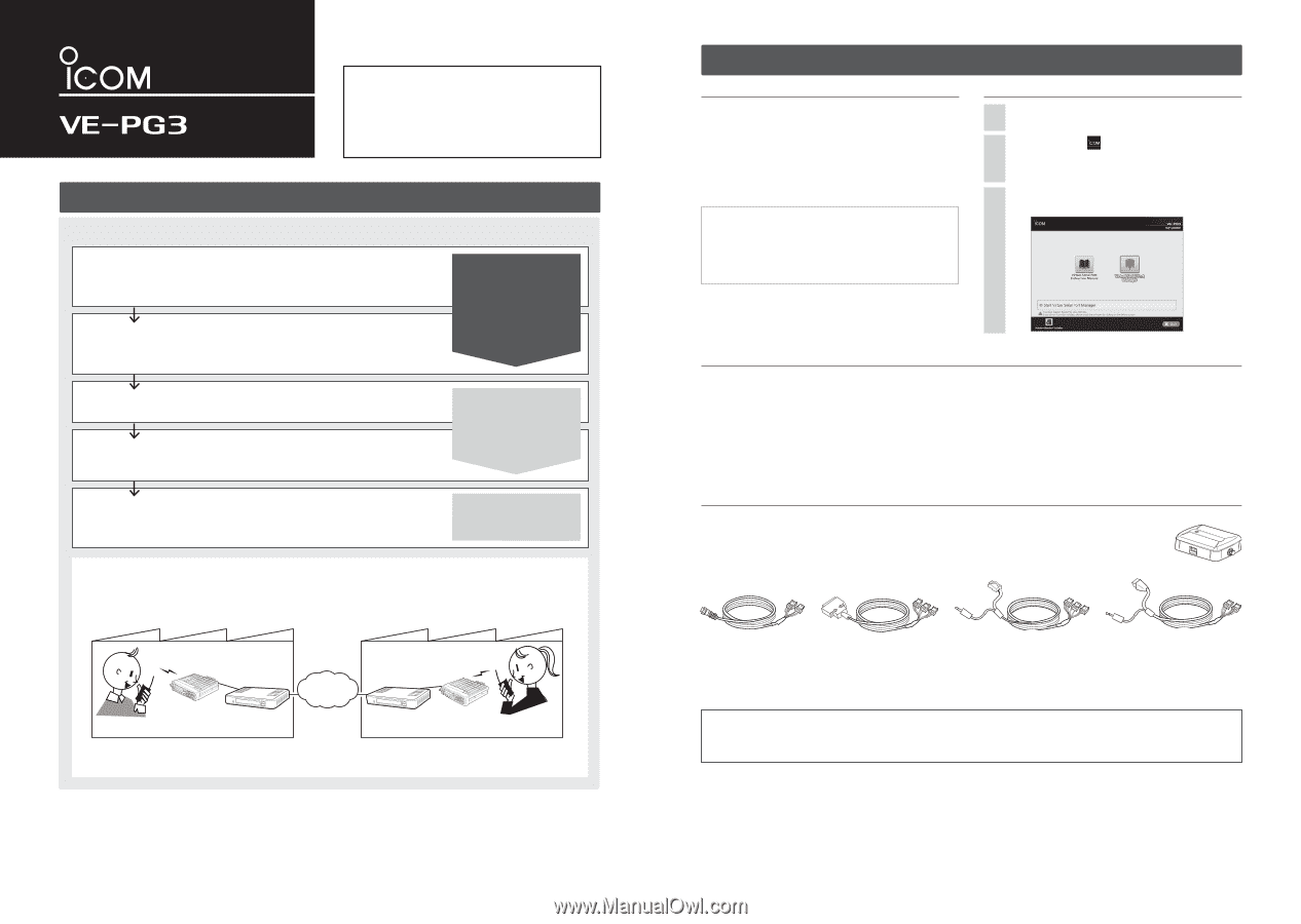
OPC-2273
CONNECTION
CABLE
for the IC-M604 (Length: approximately 5m/16.4 ft)
OPC-2274
CONNECTION
CABLE
for the IC-FR5000/FR6000 (Length: approximately 5m/16.4 ft)
OPC-2275
CONNECTION
CABLE
for the IC-F5060/F6060 (Length: approximately 5m/16.4 ft)
OPC-2276
CONNECTION
CABLE
for the Icom microphone and speaker (Length: approximately 5m/16.4 ft)
CT-24*
5
DIGITAL
VOICE
CONVERTER
to communicate using AMBE+2™ codec.
RC-FS10*
6
REMOTE
COMMUNICATOR
to create a virtual radio or simple dispatcher on a PC.
*
5
Necessary to communicate with an Icom repeater.
*
6
Allows you to access and communicate with repeaters and transceivers on your IDAS IP Network.
CT-24
The preparation procedure
Following the procedure below, setup the VE-PG3.
Step 1
Required items
• Accessories
• The supplied CD (UTILITY DISC)
• Other items as listed to the right.
• Options
Step 2
Configure the transceiver
Step 3
Configure the network
Step 5
Connect the transceiver
Step 4
Configure the VE-PG3
Set the transceiver channel and volume level.
(See the transceiver's manual for the setting de-
tails.)
Set the VE-PG3's IP address, according to your
system environment.
Connect the VE-PG3 and the transceiver, using the
appropriate optional cable.
•
Verify that both the VE-PG3 and the transceiver
are turned OFF when connecting or disconnecting
the cable.
Select the operating mode and configure the VE-
PG3, according to your operating needs.
CD (UTILITY DISC) contents
• Virtual Serial Port Manager*
1
• Virtual Serial Port Instruction Manual (PDF file)
• Adobe
®
Reader
®
Installer
*
1
Read the instruction manual for details, before attempting to
use.
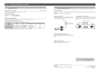
[About the operating mode]
• Converter mode
:
When communicating between a SIP phone and the transceiver through the IP network, select this
mode.
• Bridge mode (default)
:
When communicating between 2 transceivers (A1 and B1 in the illustration below) through the IP
network, select this mode.
Factory A
VE-PG3
VE-PG3
Factory B
Transceiver B
Transceiver A
An example of the Bridge mode operation
(Radio to radio communication)
IP
Network
Transceiver “A1” (Extension)
Transceiver “B1” (Extension)
Preparation
(This guide)
Installation guide 1
(Separate leaflet)
Installation guide 2
(Separate leaflet)
(You can download the Instruction Manual from the Icom web site; http://www.icom.co.jp/world/)
Continued on the back side.
Î
Insert the CD (UTILITY DISC) into a CD drive.
• You must log on as the administrator.
Double-click the
icon (APPLICATION FILE) con-
tained in the CD.
•
Depending on the PC setting, the Menu screen shown
below is automatically displayed.
1
2
The Menu screen as shown below appears.
• See the "Virtual Serial Port" PDF manual for details.
3
OPC-2273
OPC-2274
OPC-2275
OPC-2276
Read the “PRECAUTIONS” leaflet first, if you have not done so.