Icom VE-PG3 Perparation - Page 2
Step 2, Con the transceiver or repeater - instruction manual
 |
View all Icom VE-PG3 manuals
Add to My Manuals
Save this manual to your list of manuals |
Page 2 highlights
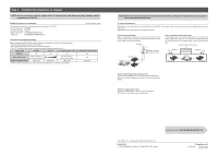
Step 2 Configure the transceiver or repeater NOTE: Set the transceiver channel, volume level, TX output power, and other necessary settings, before connecting to the VE-PG3. Usable transceivers and repeaters The following transceivers and repeaters can be used with the VE-PG3. • Marine transceiver : IC-M604 • Air band transceiver : IC-A110 • Mobile transceivers : IC-F5060/IC-F6060 series • Repeaters : IC-FR5000/IC-FR6000 series (As of December 2012) Transceiver and repeater settings Before connecting to the VE-PG3, set the transceiver and repeater as shown in the following table. • The transceiver settings affect the audio quality. • See the transceiver's instruction manual for the setting details. • Turn OFF the Power Save function to prevent missing the beginning words of a call. Model name IC-M604 IC-A110 IC-F5060/IC-F6060 series Channel any any any Audio volume level Set the volume to the 10 o'clock position. Set the volume to the 9 o'clock position. Required optional cable* OPC-2273 OPC-2275 OPC-2275 *Use the specified connection cable when connecting the transceiver or repeater to the VE-PG3. IC-FR5000/IC-FR6000 series any any OPC-2274 NOTE: When two or more transceivers are connected to the VE-PG3, separate their antennas as far as possible to reduce interference between them. To reduce interference When two or more transceivers are connected to the VE-PG3, the transmit signal from one transceiver can interfere with the other transceivers. Interference can be reduced by the methods shown below. Use the antenna directivity Even a non-directive antenna has less transmit emission in the vertical direction. When installing two antennas, mount them at different heights to reduce interference. Antenna Use a solid object as the shield screen A solid object (such as a concrete wall which has a metal frame inside, metal locker, and so on.) in between two antennas behaves like a shield screen for the transmit signal, and can reduce interference. Behaves like a shield screen. VE-PG3 Transceivers Difference in height: More than 1m; 3.3 ft Antenna Transceiver VE-PG3 Antenna Transceiver Set the channel (frequency) spacing to wide There may be interference from an adjacent channel (frequency). Setting the channel (frequency) spacing to wide can reduce interference. Set the TX output power to Low Setting the transmit power to low can reduce interference. But, note that it also reduces the coverage area. Continued on the VE-PG3 INSTALLATION 11Î The AMBE+2™ is a trademark of Digital Voice Systems, Inc. 1-1-32 Kamiminami, Hirano-ku, Osaka 547-0003, Japan A-7046W-2EX Printed in Japan © 2012 Icom Inc.
-
 1
1 -
 2
2
 |
 |
