Icom VE-PG3 Installation Instructions
Icom VE-PG3 Manual
 |
View all Icom VE-PG3 manuals
Add to My Manuals
Save this manual to your list of manuals |
Icom VE-PG3 manual content summary:
- Icom VE-PG3 | Installation Instructions - Page 1
RoIP GATEWAY INSTALLATION 2 Continued from the separate leaflet "INSTALLATION 1." Step 5 Connect the transceiver Read the "PRECAUTIONS" leaflet first, if you have not done so. Thank you for purchasing the VE-PG3. The VE-PG3 is a network converter that allows you to connect Icom radios or repeaters - Icom VE-PG3 | Installation Instructions - Page 2
LED Indication In the Converter mode In the Bridge RoIP PG3 instruction manual for details. q w e r q Link to the Icom web site Click the Icom logo to open the Icom firmware. • The USB memory is not supplied. Purchase separately. • See the VE-PG3 instruction manual for details. Turn OFF the VE-PG3
-
 1
1 -
 2
2
 |
 |
Continued on the back side.
Î
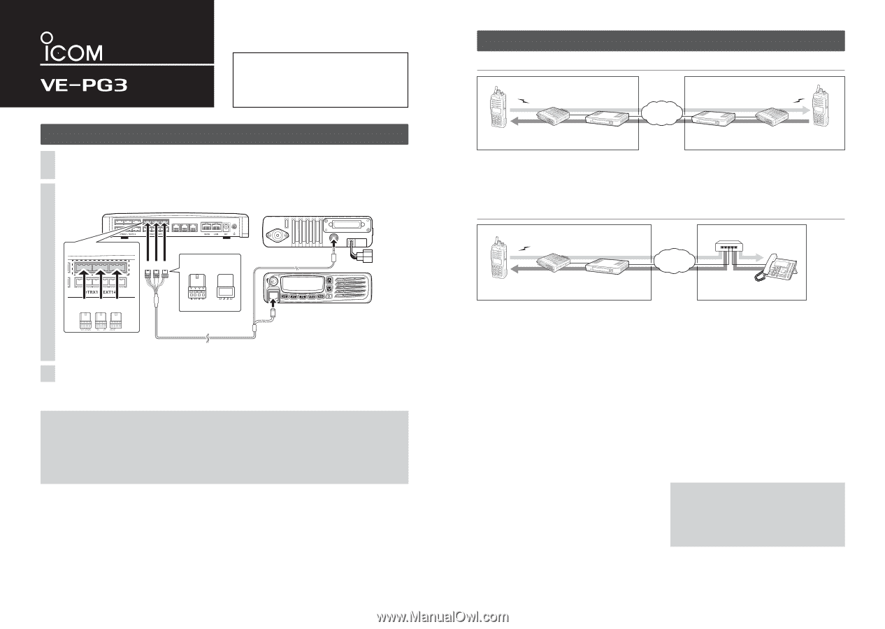
Step 5
Connect the transceiver (continued)
RoIP GATEWAY
INSTALLATION 2
VE-PG3 (Rear view)
Icom’s transceiver
(IC-F5060/IC-F6060 series)
(Rear view)
(Front view)
To the external speaker jack
To the microphone connector
LINE2
LINE1
PHONE
• This is an example to connect the transceiver to [TRX1] on the VE-PG3.
A
B
C
Be sure to insert the
connectors top side up.
Bottom
Top
A
1
2
3
4
OPC-2275
A
BC
To [TRX1] (Upper slots)
Step 5
Connect the transceiver
NOTE:
• Verify that both the radio and the VE-PG3 are turned OFF when connecting or disconnecting the transceiver.
•
Keep the radio away from a PC, AC adaptor and other electronic equipment. The noise emitted from those equipment may interfere
with the radio.
• When operating the radio, do not transmit near the IP telephone.
• If the voice level is too low, the VE-PG3 cannot detect the voice input, and the communication route will not be connected.
Set the threshold level to lower, or set the Automatic Disconnect Timer to "0" (disabled).
(See the VE-PG3's instruction manual for setting details.)
Set the transceiver channel, TX output power, and other necessary settings.
(See the transceiver's instruction manual and the “PREPARATION” leaflet for setting details.)
1
Turn OFF both the transceiver and the VE-PG3, and then connect the transceiver, as shown below.
2
Turn ON the VE-PG3 and the transceiver.
3
When using in the Bridge mode
When using in the Converter mode
[The procedure to call the IP telephone from transceiver A1.]
q
Area A
Radio A1's operator:
While holding down [PTT], say
something (example: “Test, Test, Test”) into the micro-
phone at a normal voice level.
•
The IP telephone in the area B detects the voice, and starts to
ring.
w
Area A/B
Radio A1's operator:
Release [PTT] to receive.
Person on the IP telephone:
While the IP telephone is
ringing, take the handset off the hook, and then speak
into the telephone at a normal voice level.
e
Area A/B
Radio A1's operator:
When the person on the IP tele-
phone is finished speaking, hold down [PTT] and speak
into the microphone.
[The procedure to call transceiver A1 from the IP telephone.]
q
Area B
Person on the IP telephone:
Take the handset off the
hook, dial “301,” and then speak into the telephone at a
normal voice level.
•
The communication route is connected to radio A whose ex-
tension number is “301,” and then radio A transmits the audio
to radio A1.
w
Area A/B
Radio A1's operator:
When the person on the IP tele-
phone is finished speaking, hold down [PTT], and speak
into the microphone at a normal voice level.
Release [PTT] to receive.
Person on the IP telephone:
When radio A1's operator
is finished speaking, you can start to speak again.
•
Speak only when radio A1's operator stops speaking.
Area A
Area B
VE-PG3
(192.168.0.2)
[TRX1]
[TRX1]
VE-PG3
(192.168.0.3)
Radio A
Radio A1
(Extension)
Radio B1
(Extension)
Radio B
IP
Network
All transceivers in each area must be set to the same settings.
Area A
Area B
VE-PG3
(192.168.0.2)
[TRX1]
Radio A
Radio A1
(Extension)
IP
Network
Extension No.
301
Extension number
401
HUB
All radios in the area must be set to the same settings.
[LAN]
IP telephone
(KX-UT Series)
NOTE:
• Full duplex communication is impossible.
Communicate with each other by taking turns speaking.
•
Pause briefly before you speak, to confirm your party has fin-
ished speaking.
•
The communication route will be disconnected when the IP tele-
phone's handset is put on the hook, or the VE-PG3 receives no
audio for the preset time (default: 15 seconds).
Continued from the separate leaflet “INSTALLATION 1.”
Thank you for purchasing the VE-PG3. The VE-PG3 is a
network converter that allows you to connect Icom radios
or repeaters to a VoIP network.
This guide describes the basic settings to operate the VE-PG3.
READ ALL INSTRUCTIONS carefully and completely be-
fore using.
• Radio A1 and B1 can normally communicate as if they are directly communicating in the simplex mode.
Read the “PRECAUTIONS” leaflet first, if you have not done so.