Icom VE-PG3 Installation Instructions - Page 2
For your information - firmware
 |
View all Icom VE-PG3 manuals
Add to My Manuals
Save this manual to your list of manuals |
Page 2 highlights
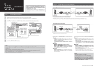
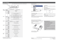
For your information About the LED indication Front view [PWR/MSG] LED (See the "PRECAUTIONS" leaflet about the and buttons.) [V/RolP] LED [TRX] (1/2) LED [USB] port (USB2.0) button [WAN] LED [D-TRX] LED [EXT] (1/2) LED LED Indication In the Converter mode In the Bridge mode PWR/MSG Doesn't light Power is OFF Green Lights Power is ON Blinks Booting Red Lights - Blinks - Orange Lights A firmware update is ready./Downloading new firmware. Blinks Accessing the USB memory. (While loading the setting file or updating the firmware.) Booting Initialization is in progress. (Green and Orange LEDs alternately light.) Firmware update is in progress. WAN Doesn't light No network connection./Connecting to the network is in progress. Green Lights Connected to the WAN line. (An IP address has been obtained.) Blinks The WAN line is communicating. Red Lights - Blinks Authentication error/failed (PPPoE) Failed to obtain IP address (DHCP) (Time-out timer: 30 seconds) Orange Lights - Blinks - V/RoIP Doesn't light No registration Not connected Green Lights Registration succeed (All entries) Connected Blinks The line is communicating. Red Lights - Blinks 1 or more registrations failed. Orange Lights - Blinks - D-TRX* Doesn't light No transceiver is connected, or it is turned OFF. Green Lights Receiving an audio signal. Blinks - Red Lights Sending an audio signal. Blinks - Orange Lights The transceiver is communicating. Blinks - TRX1 TRX2 Doesn't light Green Lights No transceiver is connected, or it is turned OFF. Receiving an audio signal. Blinks - Red Lights Sending an audio signal. Blinks - Orange Lights The transceiver is communicating. Blinks - EXT1 EXT2 Doesn't light Green Lights No input or output signal. Input is busy. Blinks - Red Lights Output is busy. Blinks - Orange Lights Input or output is busy. Blinks - *For the operation using an IC-FR5000/FR6000. • All indicators light while updating the firmware or rebooting. • The indication may differ, depending on the setting. About the setting screen • See the VE-PG3 instruction manual for details. q w e r q Link to the Icom web site Click the Icom logo to open the Icom web site if your PC is connected to the Internet. w Setting menu Displays the screen name list on a menu line. When you click each menu title, a list of items drops down which you can use to select the desire setting item. e Setting screen Displays the settings and values when you click the screen name. r Setting buttons Save or cancel setting values. If "Items that need to be restarted have changed." is displayed on the screen when you click the [Apply] button, click the [OK] button. The VE-PG3 reboots, and the setting items and values are updated. The following message is displayed on the screen while the VE-PG3 is rebooting. • If the setting screen does not automatically return, click [Back] about 30 seconds after the "Now rebooting." message appears. • Items and buttons may differ, depending on the setting. Automatic setting data load with a USB memory The setting data or firmware can be automatically loaded into the VE-PG3 from a USB memory. It is useful to recover the configuration or to update the firmware. • The USB memory is not supplied. Purchase separately. • See the VE-PG3 instruction manual for details. Turn OFF the VE-PG3's power, and then insert the USB memory securely. Then, turn ON the power again. About the USB memory • A USB memory such as one with biometric authentication, or one with password protection is not supported. • Turn OFF the VE-PG3's power before inserting or removing the USB memory, to prevent data corruption. • Either one of the USB slots accepts the USB memory, but insert only one USB memory at a time. • Inser the USB memory securely. • NEVER remove the USB memory or turn OFF the VE-PG3's power, while transferring data. It will cause data corruption, or damage the USB memory. • After the firmware updating is finished, check the firmware version on the setting screen to verify that the update was correctly done. • When importing setting data from the USB memory to the VE-PG3, the originally programmed setting data is automatically saved as "bakdata.sav" in the USB memory, as a backup. (You can download the Instruction Manual from the Icom web site; http://www.icom.co.jp/world/.) 1-1-32 Kamiminami, Hirano-ku, Osaka 547-0003, Japan A-7046W-4EX Printed in Japan © 2012 Icom Inc.
-
 1
1 -
 2
2
 |
 |
