Image Fitness 15.0 Treadmill English Manual - Page 9
Cover the Upright Wire 42 with the Right Grip Plate
 |
View all Image Fitness 15.0 Treadmill manuals
Add to My Manuals
Save this manual to your list of manuals |
Page 9 highlights
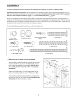
7. Cover the Upright Wire (42) with the Right Grip Plate 7 (36). Be careful not to pinch the Upright Wire. Tighten three 1/2" Screws (48) into the Right Grip Plate and the Console Base. Attach the Left Grip Plate (34) over the ground wire and the other wires with three 1/2" Screws (48). Be careful not to pinch any of the wires. 47 42 36 34 Ground Wire 48 48 8. Lower the Uprights (9, 61) until the handrails are touching the floor. 8 See the lower drawing. Position the Uprights (9, 61) so that the treadmill Frame (86) is centered between them. See the upper drawing. Firmly tighten the four 3" Bolts (37). Then, raise the Uprights (9, 61) back to the vertical position. Handrail 37 9, 61 Top View 9 61 86 9. Attach the Storage Latch (29) and the Latch Spacer (44) 9 to the Left Upright (61) with two 3/4" Screws (2) as shown. Do not overtighten the Screws. 61 29 44 2 10. Make sure that all parts are properly tightened before you use the treadmill. Note: Extra hardware may be included. Keep the included allen wrench in a secure place. The allen wrench is used to adjust the walking belt (see page 18). To protect the floor or carpet, place a mat under the treadmill. 9
-
 1
1 -
2
-
3
-
 4
4 -
 5
5 -
 6
6 -
 7
7 -
 8
8 -
 9
9 -
 10
10 -
 11
11 -
 12
12 -
 13
13 -
 14
14 -
15
-
16
-
17
-
18
-
19
-
20
-
21
-
22
 |
 |
