Image Fitness 17.5s Treadmill English Manual - Page 10
Do not overtighten the Frame Bolts., View from Above, Side View
 |
View all Image Fitness 17.5s Treadmill manuals
Add to My Manuals
Save this manual to your list of manuals |
Page 10 highlights
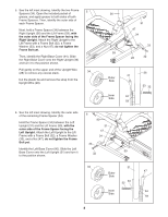
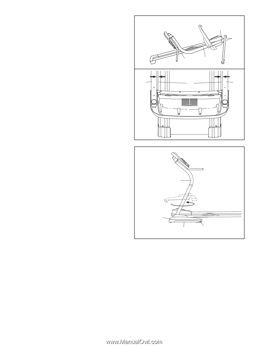
10. Lower the Uprights (31, 36). 10 See the inset drawing. Position the Uprights (31, 36) so that the treadmill Frame (74) is centered between the Uprights. Firmly tighten the Upright Bolts (27) and the Frame Bolts (32) on each side of the treadmill. Do not overtighten the Frame Bolts. 31 Side View 32 27 74 31, 36 View from Above 74 36 11. Raise the Uprights (31, 36). 11 Rotate the Left and Right Base Covers (90, 91) 180°. Slide the Base Covers over the Base (48). If necessary, pull out on the sides of the Base Covers to fit them over the Wheel Bolts (14). 31, 36 90, 91 48 14 10
-
 1
1 -
2
-
3
-
4
-
 5
5 -
 6
6 -
 7
7 -
 8
8 -
 9
9 -
 10
10 -
 11
11 -
 12
12 -
 13
13 -
 14
14 -
 15
15 -
16
-
17
-
18
-
19
-
20
-
21
-
22
-
23
-
24
-
25
-
26
 |
 |
10. Lower the Uprights (31, 36).
See the inset drawing. Position the Uprights (31,
36) so that the treadmill Frame (74) is centered
between the Uprights.
Firmly tighten the Upright Bolts (27) and the
Frame Bolts (32) on each side of the treadmill.
Do not overtighten the Frame Bolts.
36
31, 36
32
74
74
31
View from Above
Side View
10
27
11. Raise the Uprights (31, 36).
Rotate the Left and Right Base Covers (90, 91)
180°. Slide the Base Covers over the Base (48).
If necessary, pull out on the sides of the Base
Covers to fit them over the Wheel Bolts (14).
90, 91
48
11
31, 36
14
10