Image Fitness 6.0 Ex Instruction Manual - Page 7
Maintenance And Troubleshooting
 |
View all Image Fitness 6.0 Ex manuals
Add to My Manuals
Save this manual to your list of manuals |
Page 7 highlights
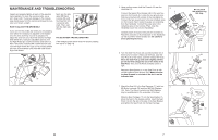
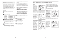
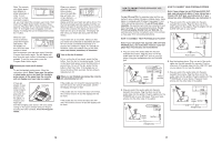
MAINTENANCE AND TROUBLESHOOTING Inspect and properly tighten all parts of the exercise cycle regularly. To clean the exercise cycle, use a soft, damp cloth. To prevent damage to the console, keep liquids away from the console and keep the console out of direct sunlight. HOW TO ADJUST THE DRIVE BELT If you can feel the pedals slip whilst you are pedaling, even when the resistance is adjusted to the highest level, the drive belt may need to be adjusted. To adjust the drive belt, you must first remove the Right Side Shield (27). Using an adjustable spanner, turn the Right Pedal (21) counterclockwise and remove it. Next, remove the indicated M4 x 25mm Screws (58). Turn the Right Crank Arm (23) so it is pointing toward the front of the exercise cycle, and then slide off the Right Side Shield. Next, turn the indicated M8 Nylon Locknut (38) until the Drive Belt (47) is properly tightened. Then, reattach the right side shield. 47 38 PULSE SENSOR TROUBLESHOOTING If the handgrip pulse sensor does not function properly, see step 5 on page 12. 58 27 23 21 58 22 5. Have another person hold the Console (4) near the Handlebar (3). Connect the Upper Wire Harness (42) to the wire harness on the Console (4). Locate the two ground wires that are connected with a screw to the Handlebar (3). Connect the two ground wires to the two smallest wires on the Console. Next, locate the pulse wire extending from the Handlebar. Connect the pulse wire to the remaining wire on the Console. Then, snap the Handlebar Cover (5) onto the Handlebar. Carefully insert all excess wiring into the Console (4). Attach the Console to the metal plate on the Handlebar (3) with four M4 x 16mm Screws (57). Be careful to avoid pinching the wires. 5 4 3 57 6. Turn the Seat Post Knob (20) counterclockwise two or 6 three turns to loosen it. Next, pull the Knob, raise the Seat Post (8) a few inches, and then release the Knob. Move the Seat Post up and down slightly until the pin on the Knob snaps into one of the holes in the Seat Post. Then, turn the Knob clockwise until it is tight. Attach the Seat Bracket (7) to the Seat Post (8) with two M8 x 25mm Patch Screws (59). Make sure that the Seat Bracket is oriented so the slot is on the indicated side. Do not pinch the wires during this step. Ground 5 Wires 42 Pulse Wire 59 7 Slot 8 20 7. Attach the Seat (9) to the Seat Carriage (11) with four 7 M8 Nylon Locknuts (38) and four M8 Split Washers (55). Note: The Nylon Locknuts and Split Washers may be preattached to the underside of the Seat. Slide the Seat Carriage (11) into the Seat Bracket (7). Move the Seat to the desired position. Insert the Seat Knob (10) into the slot in the side of the Seat Bracket, and tighten the Seat Knob into the Seat Carriage. 9 7 11 55 10 38 7
-
 1
1 -
 2
2 -
 3
3 -
 4
4 -
 5
5 -
 6
6 -
 7
7 -
 8
8 -
 9
9 -
 10
10 -
 11
11 -
 12
12 -
13
-
14
 |
 |
