InSinkErator Model WX-300 Owners Manual
InSinkErator Model WX-300 Manual
 |
View all InSinkErator Model WX-300 manuals
Add to My Manuals
Save this manual to your list of manuals |
InSinkErator Model WX-300 manual content summary:
- InSinkErator Model WX-300 | Owners Manual - Page 1
in minor personal injury or property damage. Please be certain that the person who installs or uses this appliance carefully reads and understands the Safety Instructions contained in this manual. Part No. 14481 - May 2006 - InSinkErator Model WX-300 | Owners Manual - Page 2
15 Operating Waste Xpress System 16 Operational Tips 16 Cleaning Instruction 17 Troubleshooting System Troubleshooting 18 Disposer Troubleshooting 20 Waste Xpress Troubleshooting 21 Wiring Diagrams Model No. WX-101A-1 (120V, 1 phase 22 Model No. WX-101A-2 (208/230V, 1 phase 24 Model - InSinkErator Model WX-300 | Owners Manual - Page 3
is 85% less in volume (see Figure 1 for typical installation). Important - These installation instructions are for the benefit of the installing contractor. InSinkErator and/or InSinkErator Factory Authorized Service Centers do not make original installations. For technical information not covered in - InSinkErator Model WX-300 | Owners Manual - Page 4
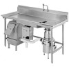
Waste Xpress Features FEATURES COMPACT SIZE The Waste Xpress® is designed to fit under a 34" high commercial kitchen table. WASTE REDUCTION Reduces volume by 85%. SAFETY INTERLOCK The Waste Xpress is equipped with safety interlock on the discharge chute (see Figure 2). This interlock prevents the - InSinkErator Model WX-300 | Owners Manual - Page 5
. AUTOMATIC TIMED DISPOSER SHUTOFF This water saving feature allows the system to run for 10 minutes before it automatically shuts off and must be manually restarted. LINE DISCONNECT SWITCH The switch on the front panel of the control center disconnects the line voltage. It interlocks with the front - InSinkErator Model WX-300 | Owners Manual - Page 6
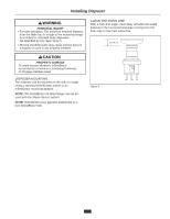
Installing Disposer PERSONAL INJURY • For safe operation, The minimum required distance from the table top or trough to the mounting flange is 6 inches for standard body disposers (as specified by UL). See Figure 5. • Moving shredder parts may cause serious injury if a hopper or cone is not properly - InSinkErator Model WX-300 | Owners Manual - Page 7
connections. If disposer legs are included, adjust the legs to support the disposer. #6 Collar Adaptor (1) Mounting Flange (2) Mounting Gasket is required. The special mountings are described in the Mounting Adaptor Selection Guide (for more information, call 1-800-845-8345 or go to www. - InSinkErator Model WX-300 | Owners Manual - Page 8
Installing the Waste Xpress Figure 11. Top View Sink Bowl Syphon Breaker Cold Water Solenoid Hot Water Solenoid Disposer WX-101A Controller Flow Control Valve Shut Off Valve Figure 12. Typical Installation Diagram 9 Waste Xpress - InSinkErator Model WX-300 | Owners Manual - Page 9
Xpress WASTE XPRESS LOCATION NOTE: Prior to installing the Waste Xpress the disposer and control center should be installed as specified within this manual. • Position Waste Xpress within 10 feet of the disposer outlet flange. A maximum of four (4) 90º elbows can be used between the disposer and - InSinkErator Model WX-300 | Owners Manual - Page 10
Plumbing Connections PROPERTY DAMAGE Water connections must comply with all local plumbing codes. WASTE INLET LINE Connect the disposer outlet flange as close as possible and with as few as possible 90° elbows to the Waste Xpress inlet. NOTE: The maximum allowable distance between the disposer - InSinkErator Model WX-300 | Owners Manual - Page 11
arrows marked on each valve body. NOTE: In-line hot and cold shutoff valves are recommended close to the Waste Xpress system for ease of service. ROUTING WATER FLOW Connect cold water only to disposer, bowl, or trough. Connect hot water only to Waste Xpress for hot water spray nozzles. In - InSinkErator Model WX-300 | Owners Manual - Page 12
the appropriate voltage and phase wiring diagram(s) in the Wiring Diagram section at the end of this manual. A wiring diagram is also located on the inside door of the control center. Wire the Waste Xpress. PERSONAL INJURY Disconnect electricity at line disconnect switch before servicing system. 13 - InSinkErator Model WX-300 | Owners Manual - Page 13
Operating Instructions PRE-OPERATION TEST Before operating the Waste Xpress complete the when front cover/discharge chute is removed, interlock may not be wired correctly. See Troubleshooting section for corrective action. ELECTRICAL SHOCK Turn off electrical supply to Waste Xpress, control - InSinkErator Model WX-300 | Owners Manual - Page 14
Instructions TO switches should be moved to match the filled in areas of the guide. NOTE: Line disconnect should not be turned off between usage. of the circuit board (see Figure 22). Move the #5 dip switch from MANUAL to AUTOMATIC. The system now automatically shuts off 10 minutes after it starts - InSinkErator Model WX-300 | Owners Manual - Page 15
Operating Instructions OPERATING WASTE XPRESS SYSTEM 1. Make sure there are no foreign objects in disposer grind chamber. Do not pre-load disposer with food waste prior to - InSinkErator Model WX-300 | Owners Manual - Page 16
Cleaning Instructions PERSONAL INJURY Wait until auger paddles stop before cleaning Waste Xpress. 1. Press stop button on control center to stop system (disposer & Waste Xpress). 2. Holding both - InSinkErator Model WX-300 | Owners Manual - Page 17
is listed below should be performed by a qualified service person. Troubleshooting performed by untrained personnel could result in electrical shock or damage to the Waste Xpress, disposer and/or Control Center. SYSTEM TROUBLESHOOTING PROBLEM POSSIBLE CAUSE The Waste Xpress, disposer and water do - InSinkErator Model WX-300 | Owners Manual - Page 18
Troubleshooting SYSTEM TROUBLESHOOTING PROBLEM Waste Xpress stops unexpectedly. POSSIBLE CAUSE • Discharge chute trough applications). • Call service. • Call service. • Remove clog. • Turn on water. • Call service. • Replace nozzles. • Call service. • Call service. • Reinstall solenoid valve - InSinkErator Model WX-300 | Owners Manual - Page 19
Troubleshooting DISPOSER TROUBLESHOOTING PROBLEM Disposer motor will not start and water does not flow. If disposer runs for 10 minutes then shuts off, the automatic shutoff is active. If the manual setting is desired, change indicated in the feature section. • Disposer is jammed. • Press stop - InSinkErator Model WX-300 | Owners Manual - Page 20
WASTE XPRESS TROUBLESHOOTING PROBLEM Auger runs in Counterclockwise (CCW) direction. POSSIBLE CAUSE • 14 to refer to dipswitch setting instructions. If the Waste Xpress remains inoperative after following this troubleshooting guide, contact InSinkErator's service department at 1-800-845-8345 for - InSinkErator Model WX-300 | Owners Manual - Page 21
. • The disposer motor wiring connection is shown in the disposer terminal box. 120 V 1-phase Call Toll Free 1-800-845-8345 for the nearest InSinkErator Authorized Service Agency or to reach Technical Support. 22 - InSinkErator Model WX-300 | Owners Manual - Page 22
WX101A-1 120V, 1Phase Electrical Connections 23 - InSinkErator Model WX-300 | Owners Manual - Page 23
disposer motor wiring connection is shown in the disposer terminal box. 208/230 V 1-phase Call Toll Free 1-800-845-8345 for the nearest InSinkErator Authorized Service Agency or to reach Technical Support. 24 - InSinkErator Model WX-300 | Owners Manual - Page 24
WX101A-2 208/230V 1Phase Electrical Connections 25 - InSinkErator Model WX-300 | Owners Manual - Page 25
connection is shown in the disposer terminal box. 120 V 210-8p/h2a3s0eV 1/32-ptoha2sHeP Call Toll Free 1-800-845-8345 for the nearest InSinkErator Authorized Service Agency or to reach Technical Support. 26 - InSinkErator Model WX-300 | Owners Manual - Page 26
WX101A-3 208/230V 3Phase Electrical Connections 27 - InSinkErator Model WX-300 | Owners Manual - Page 27
connection is shown in the disposer terminal box. 120 V 318-0p/h4a6s0eV 1/32-ptoha2sHeP Call Toll Free 1-800-845-8345 for the nearest InSinkErator Authorized Service Agency or to reach Technical Support. 28 - InSinkErator Model WX-300 | Owners Manual - Page 28
WX101A-4 380/460V 3Phase Electrical Connections 29 - InSinkErator Model WX-300 | Owners Manual - Page 29
Motor Wiring Diagrams Figure 29. 208-230 volt - 3 Phase 460 volt - 3 Phase Figure 30. 115 volt - 1 Phase 208-230 volt - 1 Phase 30 - InSinkErator Model WX-300 | Owners Manual - Page 30
-
 1
1 -
 2
2 -
 3
3 -
 4
4 -
 5
5 -
 6
6 -
 7
7 -
8
-
9
-
10
-
11
-
12
-
13
-
14
-
15
-
16
-
17
-
18
-
19
-
20
-
21
-
22
-
23
-
24
-
25
-
26
-
27
-
28
-
29
-
30
 |
 |

Part No. 14481 - May 2006
www.insinkerator.com
Please be certain that the person who installs or uses this appliance carefully
reads and understands the Safety Instructions contained in this manual.
The
Danger
signal indicates an immediately hazardous situation which,
if not avoided,
will
result in death or serious injury.
The
Warning
signal alerts you to potential hazards or unsafe practices which,
if not avoided,
could
result in severe personal injury or death.
The
Caution
signal alerts you to hazards of unsafe practices which, if not avoided,
may
result in minor personal injury or property damage.