Intel 630 User Manual - Page 23
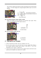
IDE Activity LED: HDLED, Turbo LED switch: TBLED, Reset switch lead: RST, Power LED, Power switch
 |
UPC - 683728086404
View all Intel 630 manuals
Add to My Manuals
Save this manual to your list of manuals |
Page 23 highlights
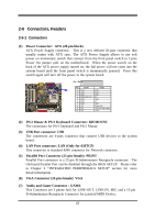
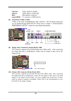
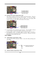
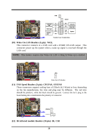
These headers are used for connecting the additional USB port plug. By attaching an option USB cable, your can be provided with two additional USB plugs affixed to the back panel. Pin 1 USB2 (3) IDE Activity LED: HDLED This connector connects to the hard disk activity indicator light on the case. (4) Turbo LED switch: TBLED Since the motherboard's turbo function is always on. The turbo LED will remain constantly on while the system power is on. You may wish to connect the Power LED from the system case to this lead. See the figure below. (5) Reset switch lead: RST This 2-pin connector connects to the case-mounted reset switch for rebooting your computer without having to turn off your power switch. This is a preferred method of rebooting in order to prolong the lift of the system's power supply. See the figure below. (6) Keyboard lock switch: KEYLOCK This 2-pin connector connects to the case-mounted key switch for locking the keyboard for security purposes. (7) Speaker connector: SPKR This 4-pin connector connects to the case-mounted speaker. See the figure below. (8) Power LED: PWR LED The Power LED is light on while the system power is on. Connect the Power LED from the system case to this pin. (9) Power switch: PWR This 2-pin connector connects to the case-mounted power switch to power ON/OFF the system. 20
-
 1
1 -
2
-
3
-
4
-
5
-
6
-
7
-
8
-
9
-
10
-
11
-
12
-
13
-
14
-
15
-
16
-
17
-
 18
18 -
 19
19 -
 20
20 -
 21
21 -
 22
22 -
 23
23 -
 24
24 -
 25
25 -
 26
26 -
 27
27 -
 28
28 -
29
-
30
-
31
-
32
-
33
-
34
-
35
-
36
-
37
-
38
-
39
-
40
-
41
-
42
-
43
-
44
-
45
-
46
-
47
-
48
-
49
-
50
-
51
-
52
-
53
-
54
 |
 |
