Intel 945G User Manual
Intel 945G - Bulk Single Unit Atx Exp Manual
 |
UPC - 735858177825
View all Intel 945G manuals
Add to My Manuals
Save this manual to your list of manuals |
Intel 945G manual content summary:
- Intel 945G | User Manual - Page 1
Intel® 945G Express Chipset Development Kit User's Manual April 2007 Reference #308823-002 - Intel 945G | User Manual - Page 2
features or instructions marked "reserved" or "undefined." Intel reserves these for future definition and shall have no responsibility whatsoever for conflicts or incompatibilities arising from future changes to them. The Intel® 945G Express Chipset Development Kit User's Manual may contain design - Intel 945G | User Manual - Page 3
Hardware Lists 14 Software Key Features ...14 AMI* BIOS...14 Processor Features and Operation 15 Intel® Pentium® 4 Processor 551 15 Intel® Celeron® D Processor 341 16 Intel® 945G Express Chipset Features and Operation 16 Intel® 945G Memory Controller Hub ((G)MCH 17 Intel® I/O Controller Hub - Intel 945G | User Manual - Page 4
Intel® 945G Express Chipset Development Kit User's Manual Contents 4.4.1 4.4.2 4.4.3 4.4.4 4.4.5 4.4.6 4.4.7 4.4.8 4.4.9 4.5 Evaluation Board Headers 48 ATX Power Connectors 49 IDE Connector...50 SATA Pinout ...50 Fan Connectors...51 Front Panel USB Header 51 Front Panel Audio Header 51 Front - Intel 945G | User Manual - Page 5
Intel® 945G Express Chipset Development Kit User's Manual Contents Table 14 Table 15 Table 16 Table 17 Table 18 Table 19 Table 20 Table 21 Table 22 Table 23 Table 24 Table 25 Table 26 Table 27 Table 28 Table 29 Table 30 Table 31 Table 32 Back Panel I/O Connectors 41 Core Panel Audio Header 51 - Intel 945G | User Manual - Page 6
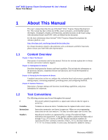
Intel® 945G Express Chipset Development Kit User's Manual About This Manual 1 About This Manual This user's manual describes the use of the Intel® 945G® Express Chipset Development Kit. This manual has been written for OEMs, system evaluators, and embedded system developers. All jumpers, headers, - Intel 945G | User Manual - Page 7
. Term ADD2+ Card ACPI BLT Core CRT DBI DDR DDR2 DMI DVI FSB Full Reset Description Advanced Digital Display Card - 2nd Generation. Provides digital display options for an Intel graphics controller that supports ADD2+ cards. It plugs into a x16 PCI Express* connector but uses the multiplexed SDVO - Intel 945G | User Manual - Page 8
Intel® 945G Express Chipset Development Kit User's Manual About This Manual Term GMCH Host Intel® DVO Intel® ICH7 LCD LVDS MCH MEC PCI Express Primary PCI SDVO SDVO Device SMI UMA Description Graphics Memory Controller Hub. Component that contains the processor interface, DRAM controller, x16 PCI - Intel 945G | User Manual - Page 9
Intel® 945G Express Chipset Development Kit User's Manual About This Manual 1.4 1.4.1 1.4.2 1.5 Table 1 Support Options Electronic Support Systems Intel's site on the World Wide Web (http://www.intel.com/) provides up-to-date technical information and product support. This information is - Intel 945G | User Manual - Page 10
Thermal Design Guide Intel® Celeron D Processor in the 775-Land LGA Package for Embedded Applications Thermal Design Guide Intel® 945G/945P Express Chipset Family Datasheet Intel® 945G/P Express Chipset Family Memory Controller Hub Specification Update Intel® 945G/P Express Chipset Family Thermal - Intel 945G | User Manual - Page 11
Controller Hub 7 (ICH7) Family for the I/O subsystem. Figure 1 shows an example system block diagram for the 945G Express Chipset. Intel® 945G/ICH7 Platform Block Diagram Processor Display PCI Express Gigabit Ethernet VGA Analog Display Display MEC Display SDVO OR Graphics Card PCI Express - Intel 945G | User Manual - Page 12
Intel® 945G Express Chipset Development Kit User's Manual Development Kit Features 2.1.1 Table 3 Intel® 945G Express Platform Features and Benefits The 945G Express platform is designed to support several processor types: Intel® Pentium® 4 Processor on 90nm Process in the 775-land LGA Package and - Intel 945G | User Manual - Page 13
Intel® 945G Express Chipset Development Kit User's Manual Development Kit Features 2.1.2 Table 4 Development Kit Features Summary This section summarizes the actual development kit features. Development Kit Features Summary Form Factor Processor Memory Chipset Video Audio Legacy I/O Control - Intel 945G | User Manual - Page 14
Fan speed control 2.2 2.3 Note: Note: 2.3.1 Development Kit Hardware Lists The following hardware is included in the development kit: • 1x Intel® 945G Express Chipset Development Kit reference board. • 1x Intel® Pentium® 4 Processor 551 with HT Technology (at 3.4 GHz) • 1x Pre-installed CPU fan - Intel 945G | User Manual - Page 15
Intel® 945G Express Chipset Development Kit User's Manual Development Kit Features 2.4 2.4.1 Processor Features and Operation The following section provides a detailed view at processor features and operation. Intel® Pentium® 4 Processor 551 The main different between the Pentium 4 processor 550 - Intel 945G | User Manual - Page 16
Intel® 945G Express Chipset Development Kit User's Manual Development Kit Features 2.4.2 Note: 2.5 ⎯ System Management mode ⎯ Multiple low-power states • Optimized for 32-bit applications running on advanced 32-bit operating systems Intel® Celeron® D Processor 341 This processor is not available - Intel 945G | User Manual - Page 17
Kit User's Manual Development Kit Features 2.5.1 2.5.1.1 2.5.1.2 2.5.1.3 Intel® 945G Memory Controller Hub ((G)MCH) The Intel® 945G Express Chipset (G)MCH provides the processor interface optimized for Intel Pentium 4 Processors, system memory interface, DMI, and internal/external graphics. It - Intel 945G | User Manual - Page 18
Intel® 945G Express Chipset Development Kit User's Manual Development Kit Features 2.5.1.4 Specification, Revision 1.0a. The x16 port operates at a frequency of 2.5 Gbits/s on each lane while employing 8b/10b encoding, and supports a maximum theoretical bandwidth of 4 GBytes/s in each direction. - Intel 945G | User Manual - Page 19
Intel® 945G Express Chipset Development Kit User's Manual Development Kit Features 2.5.1.5 Analog and Serial Digital Video Out (SDVO) Displays The (G)MCH provides interfaces to a progressive scan analog monitor and two SDVO ports (multiplexed with PCI Express x16 graphics port signals) capable of - Intel 945G | User Manual - Page 20
Intel® 945G Express Chipset Development Kit User's Manual Development Kit Features PCI Express* Interface The ICH7 has 4x PCI Express root ports (ports 1-4), supporting the PCI Express Base Specification, Revision 1.0a. PCI Express root ports 1-4 can be statically configured as four x1 ports or - Intel 945G | User Manual - Page 21
Intel® 945G Express Chipset Development Kit User's Manual Development Kit compatible with most I2C devices. Special I2C commands are implemented. The ICH7's SMBus host controller provides a mechanism for the processor to initiate communications with SMBus peripherals (slaves). Also, the ICH7 supports - Intel 945G | User Manual - Page 22
Intel® 945G Express Chipset Development Kit User's Manual Development Kit Features Table 5 Effects of Power Switch Pressing Duration If the system is in this state... Off (ACPI G2/G5 - soft off) On (ACPI - Intel 945G | User Manual - Page 23
Intel® 945G Express Chipset Development Kit User's Manual Intel® Pentium® 4 Processor 551 with HT Technology†, the Intel® 945G Express Chipset -resolution monitor. The setup instructions in this section assume that drivers and correctly configure any software for video adapters used. Check the BIOS - Intel 945G | User Manual - Page 24
Intel® 945G Express Chipset Development Kit User's Manual much like a standard desktop computer motherboard. Most PC-compatible peripherals can be attached and configured for more detail on the memory configurations. a. 1x 3.4 GHz Intel® Pentium® 4 Processor 551 b. 1x CPU thermal solution c. At least - Intel 945G | User Manual - Page 25
Intel® 945G Express Chipset Development Kit User's Manual Setting Up the Development Kit Note: a. Insert a the audio speakers. Please refer to Section 3.3.2 for more detail on audio setup. 14. (Optional) Connect an Ethernet cable. Please refer to Section 3.3.3 for more detail on the LAN subsystem. - Intel 945G | User Manual - Page 26
Intel® 945G Express Chipset Development Kit User's Manual Setting Up the Development Kit 26 Reference #308823 - Intel 945G | User Manual - Page 27
Intel® 945G Express Chipset Development Kit User's Manual Setting Up the Development Kit Figure 2 Memory Channel and DIMM Configuration 3.3.1.1 Figure 3 Dual Channel (Interleaved) Mode Configurations Figure 3 shows a dual channel configuration using two DIMMs. In this example, the DIMM 0 sockets - Intel 945G | User Manual - Page 28
Intel® 945G Express Chipset Development Kit User's Manual Setting Up the Development Kit Figure 5 Dual Channel (Interleaved) with 3x DIMMs 3.3.2 Audio Subsystem Configurations The board supports the Intel® High Definition Audio subsystem based on the Realtek ALC882 audio codec. The ALC882 series - Intel 945G | User Manual - Page 29
Intel® 945G Express Chipset Development Kit User's Manual Setting Up the Development Kit 3.3.2.1 Figure 8 The board contains audio connectors on the back panel and two channels of independent stereo sound output at the side of the board. The functions of the back panel audio connectors are - Intel 945G | User Manual - Page 30
Intel® 945G Express Chipset Development Kit User's Manual Setting Up the Development Kit 3.3.3.1 3.3.3.2 Figure 9 Gigabit LAN Subsystem The Gigabit (10/100/1000 Mbits/sec) LAN subsystem includes the Intel® 82573E Gigabit Ethernet Controller and an RJ-45 LAN connector with integrated status LEDs. - Intel 945G | User Manual - Page 31
Intel® 945G Express Chipset Development Kit User's Manual Setting Up the Development Kit 3.3.4 Intel® Active Management Technology (Optional) Intel Active Management Technology (AMT) offers IT organizations tamper-resistant and persistent management capabilities. Specifically, Intel® AMT is a - Intel 945G | User Manual - Page 32
Intel® 945G Express Chipset Development Kit User's Manual Setting Up the Development Kit 3.3.5 3.4 3.4.1 3.4.2 Table 8 ⎯ Operating system lock-up alert ⎯ Boot failure alert ⎯ Hardware failure alerts • Third-party non-volatile storage that prevents users - Intel 945G | User Manual - Page 33
Intel® 945G Express Chipset Development Kit User's Manual Setting Up the Development Kit 3.4.3 Table 9 BIOS Error Messages The table below show the lists of BIOS error messages and brief description of each. Error Messages Error Message CMOS Battery Low CMOS Checksum Bad Memory Size Decreased No - Intel 945G | User Manual - Page 34
Intel® 945G Express Chipset Development Kit User's Manual Setting Up the Development Kit Table 11 Range E0-FF / F0-FF E0 - EE EF boot/S3 Processor exception. Miscellaneous codes. Resume failure. Category/Subsystem Port 80h POST Codes POST Code Host Processor 10 11 12 13 Chipset 21 Memory 22 23 - Intel 945G | User Manual - Page 35
Intel® 945G Express Chipset Development Kit User's Manual Setting Up the Development Kit POST Code Description of POST Operation 72 Enabling the VGA controller. Remote Console 78 Resetting the console controller. 79 Disabling the console controller. 7A Enabling the console controller. - Intel 945G | User Manual - Page 36
Intel® 945G Express Chipset Development Kit User's Manual Setting Up the Development Kit Table 12 POST Code Description of POST Operation DXE Drivers E7 Waiting for user input. E8 Checking password. E9 Entering BIOS setup. EA TBD - Flash Update. EB Calling Legacy Option ROMs. EE TBD - Intel 945G | User Manual - Page 37
Intel® 945G Express Chipset Development Kit User's Manual Setting Up the Development Kit POST EB 58 5A 92 90 94 5A 28 90 94 E7 01 00 Code Description Calling video BIOS. Resetting USB bus. Resetting PATA/SATA bus and all devices. Detecting the presence of the keyboard. Resetting keyboard. Clearing - Intel 945G | User Manual - Page 38
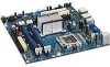
Intel® 945G Express Chipset Development Kit User's Manual Hardware References 4 Hardware References 4.1 Figure 10 Overview This section provides settings. Figure 10 and Figure 11 provide an overview of the Intel® 945G Express Chipset motherboard. Evaluation Board Layout 38 Reference #308823 - Intel 945G | User Manual - Page 39
Intel® 945G Express Chipset Development Kit User's Manual Hardware References 4.1.1 Figure 11 Board Layout Figure 11 shows the location of the major components. Evaluation Board Major Components Table 13 The table below describes the lists of components identified above. Evaluation Board - Intel 945G | User Manual - Page 40
Intel® 945G Express Chipset Development Kit User's Manual Hardware References Item / Callout from Figure 11 G H I J K L M O P Q R S T U V W X Y AA BB EE FF GG Description +12V power connector (ATX12V) Rear chassis fan connector LGA775 processor socket Intel® 82945G (G)MCH Processor fan connector - Intel 945G | User Manual - Page 41
Intel® 945G Express Chipset Development Kit User's Manual Hardware References 4.1.2 Figure 12 Back Panel Connectors The illustration below shows the location of the back panel connectors for boards equipped with the 8-channel (7.1) audio subsystem. The back panel connectors are color-coded. The - Intel 945G | User Manual - Page 42
Intel® 945G Express Chipset Development Kit User's Manual Hardware References 4.2.1 Table 15 Core Components Core Components Reference Designator J3E1 U4E1 U6F1 U6A1 U6J1 U4B1 U1J1 Component Description LGA775 processor socket Intel® 945G (G)MCH Intel® ICH7 Intel® 82573E 10/100/1000 Mbps - Intel 945G | User Manual - Page 43
Intel® 945G Express Chipset Development Kit User's Manual Hardware References 4.2.2.2 Table 17 PCI Express* x16 / MEC Slot The PCI Express x16 slot is following the industry PCI Express x16 connector standard. Table 17 shows the signals for PCI Express x16 or MEC (sDVO). Intel® sDVO to PCI Express - Intel 945G | User Manual - Page 44
Intel® 945G Express Chipset Development Kit User's Manual Hardware References Pin Number 30 31 32 33 34 35 36 37 38 39 40 41 42 43 44 45 46 47 48 49 50 51 52 53 54 55 56 57 58 59 60 61 62 63 Side B Side A PCI Express Function sDVO/MEC Function PCI Express Function sDVO - Intel 945G | User Manual - Page 45
Intel® 945G Express Chipset Development Kit User's Manual Hardware References 4.2.2.3 Table 18 Pin Number 64 65 66 67 68 69 70 71 72 73 74 75 76 77 78 79 80 81 82 Side B Side A PCI Express Function sDVO/MEC Function PCI Express Function sDVO/MEC Function GND GND PET12+ (or PETp12) PET12- ( - Intel 945G | User Manual - Page 46
Intel® 945G Express Chipset Development Kit User's Manual Hardware References Pin Number Side B Side A 11 WAKE# PW RGD Key 12 RSVD GND 13 GND REFCLK+ 14 HSOP0 REFCLK- 15 HSON0 GND 16 GND - Intel 945G | User Manual - Page 47
Intel® 945G Express Chipset Development Kit User's Manual Hardware References 4.3.1 Table 19 Table 20 Jumper Settings Jumpers Reference Designators J1J1 J6J3 J6J4 J3601 J3602 Description Force On- Slot occupied jumper for tricking the CPU socket to there is a CPU when standby and core power is - Intel 945G | User Manual - Page 48
Intel® 945G Express Chipset Development Kit User's Manual Hardware References Figure 14 Front Panel Header Table 22 Front connector Chassis fan connector CPU fan connector Floppy drive connector Front panel header Front panel USB header Front panel Audio CD audio header Intruder detection header - Intel 945G | User Manual - Page 49
Intel® 945G Express Chipset Development Kit User's Manual Hardware References 4.4.2 Table 24 ATX Power Connectors 2x12 ATX Power Connector Table 25 2x2 Auxiliary 12V Power Connector Pin Signal 1 Ground 2 Ground 3 +12 V 4 +12 V Reference #308823 49 - Intel 945G | User Manual - Page 50
Intel® 945G Express Chipset Development Kit User's Manual Hardware References 4.4.3 Table 26 IDE Connector IDE Connector 4.4.4 Table 27 SATA Pinout SATA Pinout Pin Signal 1 GND 2 TXP 3 TXN 4 GND 5 RXN 6 RXP 7 GND 50 Reference #308823 - Intel 945G | User Manual - Page 51
Intel® 945G Express Chipset Development Kit User's Manual Hardware References 4.4.5 Table 28 Fan Connectors Fan Connectors Pin Signal 1 GND 2 Ground 3 RPM 4 Control 4.4.6 Table 29 Front Panel USB Header Front Panel USB Header 4.4.7 Table 30 Front Panel Audio Header Front Panel - Intel 945G | User Manual - Page 52
Intel® 945G Express Chipset Development Kit User's Manual Hardware References 4.4.8 Table 31 Front Panel Header Front Panel Header (J7J2) 4.4.9 Serial Port Header Table 32 Serial Port Header (J2B1) Pin Signal 1 DCD 2 RXD 3 TXD 4 - Intel 945G | User Manual - Page 53
Intel® 945G Express Chipset Development Kit User's Manual Hardware References 4.5 Figure 15 Thermal Considerations The development kit is shipped with a heat sink/fan thermal solution for installation on the processor. This thermal solution has been tested in an open-air environment at room - Intel 945G | User Manual - Page 54
Intel® 945G Express Chipset Development Kit User's Manual Hardware References Figure 16 Localized High Temperature Zones 54 Reference #308823
-
 1
1 -
 2
2 -
 3
3 -
 4
4 -
 5
5 -
 6
6 -
 7
7 -
8
-
9
-
10
-
11
-
12
-
13
-
14
-
15
-
16
-
17
-
18
-
19
-
20
-
21
-
22
-
23
-
24
-
25
-
26
-
27
-
28
-
29
-
30
-
31
-
32
-
33
-
34
-
35
-
36
-
37
-
38
-
39
-
40
-
41
-
42
-
43
-
44
-
45
-
46
-
47
-
48
-
49
-
50
-
51
-
52
-
53
-
54
 |
 |

Intel
®
945G Express Chipset
Development Kit
User’s Manual
April 2007
Reference #308823-002