Intel BOXD525MW Product Guide - Page 35
Connecting to the Serial Port Header, Connecting to the Front Panel USB 2.0 Headers
 |
View all Intel BOXD525MW manuals
Add to My Manuals
Save this manual to your list of manuals |
Page 35 highlights
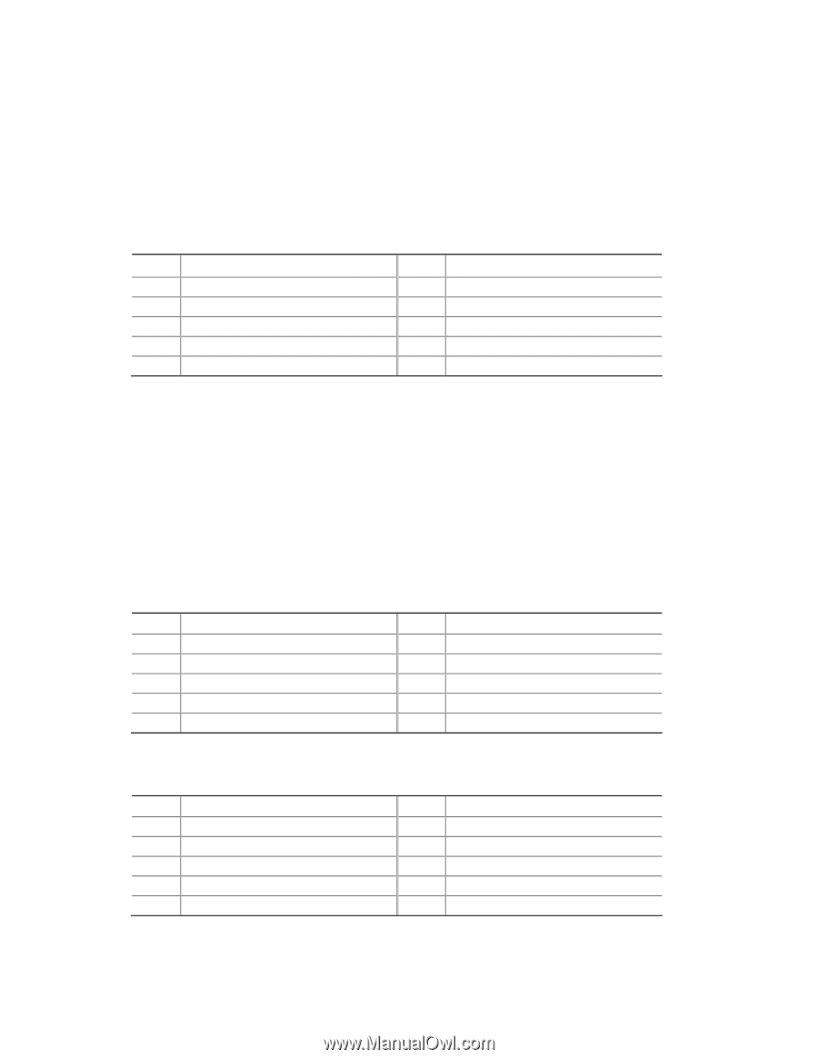
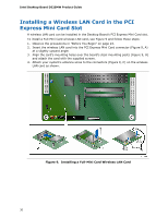
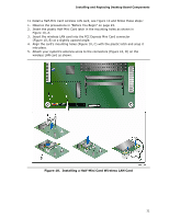
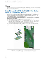
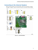
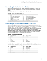
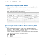
Installing and Replacing Desktop Board Components Connecting to the Serial Port Header Before connecting to the serial port header, observe the precautions in "Before You Begin" on page 23. See Figure 12, C on page 33 for the location of the serial port header. Table 8 shows the pin assignments for the serial port header. Table 8. Serial Port Header (COM 1) Pin Signal Name Pin 1 DCD (Data Carrier Detect) 2 3 TXD# (Transmit Data) 4 5 Ground 6 7 RTS (Request To Send) 8 9 RI (Ring Indicator) 10 Signal Name RXD# (Receive Data) DTR (Data Terminal Ready) DSR (Data Set Ready) CTS (Clear To Send) Key (no pin) Connecting to the Front Panel USB 2.0 Headers Before connecting to the USB 2.0 headers, observe the precautions in "Before You Begin" on page 23. See Figure 12, D and G on page 33 for the location of the USB 2.0 headers. Table 9 and Table 10 show the pin assignments for the headers. The brown USB header (Figure 12, G) supports a single USB port while the black USB header (Figure 12, D) supports two USB ports. The single USB port header is designed to support a Flash Memory Drive such as the Intel Z-U130 USB Solid-State Drive (or compatible device). Refer to Installing an Intel® Z-U130 USB Solid-State Drive or Compatible Device on page 32 for more information. Table 9. Front Panel USB Header Pin Signal Name Pin 1 +5 VDC 2 3 D- 4 5 D+ 6 7 Ground 8 9 KEY (no pin) 10 Signal Name +5 VDC DD+ Ground No Connect Table 10. Front Panel USB Header with Intel Z-U130 USB Solid-State Drive or Compatible Device Support Pin Signal Name 1 +5 VDC 3 D- 5 D+ 7 Ground 9 KEY (no pin) Pin Signal Name 2 No Connect 4 No Connect 6 No Connect 8 No Connect 10 LED# 35
-
 1
1 -
2
-
3
-
4
-
5
-
6
-
7
-
8
-
9
-
10
-
11
-
12
-
13
-
14
-
15
-
16
-
17
-
18
-
19
-
20
-
21
-
22
-
23
-
24
-
25
-
26
-
27
-
28
-
29
-
 30
30 -
 31
31 -
 32
32 -
 33
33 -
 34
34 -
 35
35 -
 36
36 -
 37
37 -
 38
38 -
 39
39 -
 40
40 -
41
-
42
-
43
-
44
-
45
-
46
-
47
-
48
-
49
-
50
-
51
-
52
-
53
-
54
-
55
-
56
-
57
-
58
-
59
-
60
-
61
-
62
-
63
-
64
 |
 |