Intel BOXDG41TY Product Guide - Page 46
S/PDIF Connector, Front Panel Audio Header, Table 5. S/PDIF Connector, Table 6.
 |
View all Intel BOXDG41TY manuals
Add to My Manuals
Save this manual to your list of manuals |
Page 46 highlights
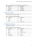
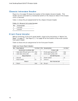
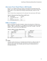
Intel Desktop Board DG41TY Product Guide S/PDIF Connector Figure 21, A on page 45 shows the location of the S/PDIF connector. Figure 5 shows the pin assignments for the S/PDIF connector. Table 5. S/PDIF Connector Pin Description 1 VCC 2 SPDIF OUT 3 Ground Front Panel Audio Header The front panel audio header shown in Figure 21, B on page 45 supports both High Definition (HD) Audio and AC'97 Audio. Table 7 shows the pin assignments and signal names for HD Audio and Table 8 shows the pin assignments and signal names for AC'97 Audio. HD Audio is the default setting for the front panel audio header. A Front Panel Audio Select jumper block is provided on the Desktop Board (see Figure 1, BB). Use the jumper to switch the header from the HD Audio pinout to the AC '97 pinout. The jumper settings are shown in Table 6. Table 6. Jumper Settings for the Front Panel Audio Select Jumper Block Jumper Setting 1-2 2-3 Audio Mode AC '97 HD Audio Table 7. Front Panel Audio Signal Names for Intel HD Audio Pin Signal Name 1 PORT 1L (Microphone) Pin Signal Name 2 GND 3 PORT 1R (Microphone) 4 PRESENCE# 5 PORT 2R (Headphone) 6 SENSE1_RETURN 7 SENSE_SEND 9 PORT 2L (Headphone) 8 KEY (no pin) 10 SENSE2_RETURN 46
-
 1
1 -
2
-
3
-
4
-
5
-
6
-
7
-
8
-
9
-
10
-
11
-
12
-
13
-
14
-
15
-
16
-
17
-
18
-
19
-
20
-
21
-
22
-
23
-
24
-
25
-
26
-
27
-
28
-
29
-
30
-
31
-
32
-
33
-
34
-
35
-
36
-
37
-
38
-
39
-
40
-
 41
41 -
 42
42 -
 43
43 -
 44
44 -
 45
45 -
 46
46 -
 47
47 -
 48
48 -
 49
49 -
 50
50 -
 51
51 -
52
-
53
-
54
-
55
-
56
-
57
-
58
-
59
-
60
-
61
-
62
-
63
-
64
-
65
-
66
-
67
-
68
-
69
-
70
-
71
-
72
-
73
-
74
-
75
-
76
 |
 |
