Intel D201GLY Product Guide
Intel D201GLY - Desktop Board Motherboard Manual
 |
UPC - 735858193702
View all Intel D201GLY manuals
Add to My Manuals
Save this manual to your list of manuals |
Intel D201GLY manual content summary:
- Intel D201GLY | Product Guide - Page 1
Intel® Desktop Board D201GLY Product Guide Order Number: D84430-001 - Intel D201GLY | Product Guide - Page 2
Revision History Revision Revision History -001 First release of the Intel® Desktop Board D201GLY Product Guide Date March 2007 If an FCC declaration of conformity marking is present on the board, the following statement applies: FCC Declaration of Conformity This device complies with Part 15 - Intel D201GLY | Product Guide - Page 3
equipment, etc. may not be supported without further evaluation by Intel. Document Organization The chapters in this Product Guide are arranged as follows: 1 Desktop Board Features: a summary of product features 2 Installing and Replacing Desktop Board Components: instructions on how to install the - Intel D201GLY | Product Guide - Page 4
Intel Desktop Board D201GLY Product Guide Terminology The table below gives descriptions to some common terms used in the product guide. Box Contents • Intel Desktop Board • I/O shield • One ATA-66/100 cable • Quick Reference Guide • Configuration and safety labels • Intel® Express Installer driver - Intel D201GLY | Product Guide - Page 5
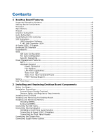
Board Features Supported Operating Systems 10 Desktop Board Components 11 Processor ...13 Main Memory ...13 Chipset ...14 Graphics Subsystem 14 Audio Subsystem 14 Input/Output (I/O) Controller 15 LAN Subsystem 15 LAN Subsystem Software 16 RJ-45 LAN Connector LEDs 16 Hi-Speed USB 2.0 Support - Intel D201GLY | Product Guide - Page 6
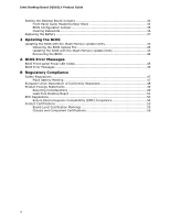
Intel Desktop Board D201GLY Product Guide Setting the Desktop Board Jumpers 34 Front Panel Audio Header/Jumper Block 34 BIOS Configuration Jumper 35 Clearing Passwords 36 Replacing the Battery 37 3 Updating the BIOS Updating the BIOS with the Iflash Memory Update Utility 43 Obtaining the BIOS - Intel D201GLY | Product Guide - Page 7
Jumpers 34 14. Removing the Battery 41 Tables 1. Feature Summary 9 2. Desktop Boards D201GLY Components 12 3. RJ-45 10/100 Ethernet LAN Connector LEDs 16 4. Front Panel Audio Header Signal Names 30 5. Hi-Speed USB 2.0 Header Signal Names 31 6. Front Panel Header Signal Names 31 7. Front - Intel D201GLY | Product Guide - Page 8
Intel Desktop Board D201GLY Product Guide viii - Intel D201GLY | Product Guide - Page 9
the main features of Intel® Desktop Board D201GLY. Table 1 summarizes the features of the Desktop Board. Table 1. Feature Summary Form Factor Processor Mini-ITX (171.45 millimeters [6.75 inches] x 171.45 millimeters [6.75 inches]) Intel® Celeron® processor Main Memory • One 240-pin SDRAM - Intel D201GLY | Product Guide - Page 10
about Desktop Board D201GLY, including the Technical Product Specification (TPS), BIOS updates, and device drivers, go to: http://support.intel.com/support/motherboards/desktop/ Supported Operating Systems The Desktop Board supports the following operating systems: • Microsoft Windows* XP - Intel D201GLY | Product Guide - Page 11
Desktop Board Features Desktop Board Components Figure 1 shows the location of the major components on Desktop Board D201GLY. Figure 1. Intel Desktop Board D201GLY Components 11 - Intel D201GLY | Product Guide - Page 12
Battery BIOS configuration jumper Related Links: Go to the following links for more information about: • Desktop Board D201GLY • Audio software and utilities • LAN software and drivers http://www.intel.com/design/motherbd http://support.intel.com/support/motherboards/desktop http://www.intel.com - Intel D201GLY | Product Guide - Page 13
x 2) power connector to the Desktop Board may result in damage to the board, or the system may not function properly. Desktop Board D201GLY includes an Intel Celeron processor. The processor is soldered to the Desktop Board and is not customer upgradeable. Main Memory NOTE To be fully compliant with - Intel D201GLY | Product Guide - Page 14
Intel Desktop Board D201GLY Product Guide Chipset The chipset used on Desktop Board D201GLY consists of the following devices: • SiS662 Graphics and Memory Controller (Northbridge) • SiS964L I/O Controller (Southbridge) Graphics Subsystem The Desktop Board D201GLY graphics subsystem features the SiS - Intel D201GLY | Product Guide - Page 15
more information about: • Audio drivers and utilities http://support.intel.com/support/motherboards/desktop/ • Installing a front panel audio solution (page 30) Input PCI power management support LAN Subsystem The LAN provides the following functions: • 10/100 Mb/s Ethernet LAN • Support for RJ-45 - Intel D201GLY | Product Guide - Page 16
Intel Desktop Board D201GLY Product Guide LAN Subsystem Software For LAN software and drivers, refer to the D201GLY link on Intel's World Wide Web site at: http://support.intel.com/support/motherboards/desktop RJ-45 LAN Connector LEDs Two LEDs are built into the RJ-45 LAN connector located on the - Intel D201GLY | Product Guide - Page 17
devices • Ultra DMA-33/66/100 modes Expandability The Desktop Board supports one PCI add-in card. BIOS The BIOS provides the Power-On Self-Test (POST), the BIOS Setup program, the PCI and IDE auto-configuration utilities, and the video BIOS. IDE Auto Configuration If you install an IDE device (such - Intel D201GLY | Product Guide - Page 18
Intel Desktop Board D201GLY Product Guide PCI Auto Configuration If you install a PCI add-in card in your computer, the PCI auto-configuration utility in the BIOS set, you can enter either password to boot the computer. Related Links: For instructions on resetting the password, see Clearing - Intel D201GLY | Product Guide - Page 19
Links: For more information on standby current requirements for the Desktop Board, refer to the Technical Product Specification by going to the following link, finding the product, and selecting Product Documentation from the left-hand menu: http://support.intel.com/support/motherboards/desktop/ 19 - Intel D201GLY | Product Guide - Page 20
Intel Desktop Board D201GLY Product Guide LAN Wake Capabilities CAUTION For LAN wake capabilities, the 5 V standby line for the power supply must be capable of delivering adequate +5 V standby current. Failure to provide adequate standby current when using - Intel D201GLY | Product Guide - Page 21
how to: • Install the I/O shield • Install and remove the Desktop Board • Install and remove memory • Connect the IDE cable • Connect internal headers • Connect chassis fan and power supply cables • Set the BIOS configuration and audio jumpers • Clear passwords • Replace the battery Before You Begin - Intel D201GLY | Product Guide - Page 22
Intel Desktop Board D201GLY Product Guide Installation Precautions When you install and test the Intel Desktop Board, observe all warnings and cautions in the installation instructions. To avoid injury, be careful of: • Sharp pins on connectors or headers • Sharp pins on printed circuit assemblies • - Intel D201GLY | Product Guide - Page 23
transmissions, protects internal components from dust and foreign objects, and promotes correct airflow within the chassis. Install the I/O shield before installing the Desktop Board in the chassis. Place the shield inside the chassis as shown in Figure 5. Press the shield into place so that it fits - Intel D201GLY | Product Guide - Page 24
Intel Desktop Board D201GLY Product Guide Installing and Removing the Desktop Board CAUTION Only qualified technical manual for instructions on installing and removing the Desktop Board. Figure 6 shows the location of the mounting screw holes for Desktop Board D201GLY. Figure 6. Desktop Board D201GLY - Intel D201GLY | Product Guide - Page 25
Serial Presence Detect (SPD) data structure. You can access the PC Serial Presence Detect Specification at: http://www.intel.com/technology/memory/ddr/specs/dda18c32_64_128x72ag_a.pdf The Desktop Board has one 240-pin DDR2 DIMM socket. Installing DIMMs To make sure you have the correct DIMM, place - Intel D201GLY | Product Guide - Page 26
Intel Desktop Board D201GLY Product Guide 1. Observe the precautions in "Before You Begin" on page 21. 2. Turn off all peripheral devices connected to the computer. Turn off the computer and disconnect - Intel D201GLY | Product Guide - Page 27
IDE Cable The IDE cable can connect two drives to the Desktop Board. The cable supports the ATA-100 transfer protocol. Figure 9 shows the correct Attach the cable end with the single connector (blue) to the Intel Desktop Board (Figure 9). 3. Attach the cable end with the two closely spaced connectors (gray - Intel D201GLY | Product Guide - Page 28
Intel Desktop Board D201GLY Product Guide Figure 9. Connecting the IDE Cable 28 - Intel D201GLY | Product Guide - Page 29
and Replacing Desktop Board Components Connecting Internal Headers Before connecting cables to the internal headers, observe the precautions in "Before You Begin" on page 21. Figure 10 shows the location of the board's internal headers. Item A B C Description Audio Hi-speed USB 2.0 (two) Front - Intel D201GLY | Product Guide - Page 30
Intel Desktop Board D201GLY Product Guide Installing a Front Panel Audio Solution Figure 10, A shows the location of the front panel audio header. Table 4 shows the pin assignments for the front panel audio header. Table 4. Front Panel Audio Header Signal Names Pin Signal Name 1 MIC 3 MIC- - Intel D201GLY | Product Guide - Page 31
Installing and Replacing Desktop Board Components Connecting Hi-Speed USB 2.0 Headers Before connecting the USB 2.0 headers, observe the precautions in "Before You Begin" on page 21. See Figure 10, B on page 29 for the location of the USB 2.0 headers. Table 5 shows the pin assignments for the - Intel D201GLY | Product Guide - Page 32
Intel Desktop Board D201GLY Product Guide Connecting the Chassis Fan Figure 11 shows the location of the chassis fan header. Connect the chassis fan cable to this header. Figure 11. Location of the Chassis Fan Header 32 - Intel D201GLY | Product Guide - Page 33
Desktop Board may result in damage to the board or the system may not function properly. Figure 12 shows the location of the power connectors. Figure 12. Connecting a 2 x 10 or 2 x 12 Power Supply Cable 1. Observe the precautions in "Before You Begin" on page 21. 2. Connect the 12 V processor - Intel D201GLY | Product Guide - Page 34
Intel Desktop Board D201GLY Product Guide Setting the Desktop Board Jumpers NOTE Always turn off the power and unplug the power cord from the computer before changing a jumper. Moving the jumper with the power on may result in unreliable computer operation. Figure 13. Desktop Board Jumpers Front - Intel D201GLY | Product Guide - Page 35
, B shows the location of the Desktop Board's BIOS configuration jumper block. Table 8. Jumper Settings for the BIOS Setup Program Modes Jumper Setting Mode Normal (default) (1-2) Description The BIOS uses the current configuration and passwords for booting. Configure (2-3) After the Power-On - Intel D201GLY | Product Guide - Page 36
Intel Desktop Board D201GLY Product Guide Clearing Passwords This procedure assumes that the board is installed in the Replace the cover, plug in the computer, turn on the computer, and allow it to boot. 7. The computer starts the Setup program. Setup displays the Maintenance menu. 8. Use the - Intel D201GLY | Product Guide - Page 37
and Replacing Desktop Board Components Replacing the Battery A coin-cell battery (CR2032) powers the real-time clock and CMOS memory. When ºC with 3.3 VSB applied. When the voltage drops below a certain level, the BIOS Setup program settings stored in CMOS RAM (for example, the date and time) might - Intel D201GLY | Product Guide - Page 38
Intel Desktop Board D201GLY Product Guide AVVERTIMENTO Esiste il pericolo di un esplosione se la pila non viene sostituita in modo corretto. Utilizzare solo pile uguali o di tipo equivalente a quelle consigliate - Intel D201GLY | Product Guide - Page 39
Installing and Replacing Desktop Board Components AWAS Risiko letupan wujud jika bateri digantikan dengan jenis yang tidak betul. Bateri sepatutnya dikitar semula jika boleh. Pelupusan bateri terpakai mestilah mematuhi peraturan - Intel D201GLY | Product Guide - Page 40
Intel Desktop Board D201GLY Product Guide O 40 - Intel D201GLY | Product Guide - Page 41
Installing and Replacing Desktop Board Components To replace the battery, follow these steps: 1. Observe (wall outlet or power adapter). 3. Remove the computer cover. 4. Locate the battery on the board (see Figure 14). 5. Push the battery retention clip aside and remove the battery from the connector - Intel D201GLY | Product Guide - Page 42
Intel Desktop Board D201GLY Product Guide 42 - Intel D201GLY | Product Guide - Page 43
computer supplier or by navigating to the Desktop Board D201GLY page on the Intel World Wide Web site at: http://support.intel.com/support/motherboards/desktop Navigate to the D201GLY page, click "[view] Latest BIOS updates," and select the Iflash BIOS Update utility file. CAUTION Do not interrupt - Intel D201GLY | Product Guide - Page 44
and manually update the BIOS. Recovering the BIOS It is unlikely that anything will interrupt the BIOS update; however, if an interruption occurs, the BIOS could be damaged. For more information about recovering the BIOS for desktop board D201GLY, go to: http://support.intel.com/support/motherboards - Intel D201GLY | Product Guide - Page 45
causes the front-panel power LED to blink an error message describing the problem (see Table 9). Table 9. Front-panel Power LED Blink Codes Type Processor initialization complete POST complete BIOS update in progress Video error Pattern On when system powers up, then off for 0.5 second On when - Intel D201GLY | Product Guide - Page 46
Intel Desktop Board D201GLY Product Guide 46 - Intel D201GLY | Product Guide - Page 47
(EMC) regulations • Product certifications Safety Regulations Desktop Board D201GLY complies with the safety regulations stated in Table ) Place Battery Marking There is insufficient space on this Desktop Board to provide instructions for replacing and disposing of the Lithium ion coin cell - Intel D201GLY | Product Guide - Page 48
Intel Desktop Board D201GLY Product Guide European Union Declaration of Conformity Statement We, Intel Corporation, declare under our sole responsibility that the product Intel® Desktop Board D201GLY is in conformity with all applicable essential requirements necessary for CE marking, following the - Intel D201GLY | Product Guide - Page 49
this program, including the scope of covered products, available locations, shipping instructions, terms and conditions, etc. Intel Product Recycling Program http://www.intel.com/intel/other/ehs/product_ecology Deutsch Als Teil von Intels Engagement für den Umweltschutz hat das Unternehmen das - Intel D201GLY | Product Guide - Page 50
Intel Desktop Board D201GLY Product Guide Details zu diesem Programm, einschließlich der darin eingeschlossenen Produkte, verfügbaren Standorte, Versandanweisungen, Bedingungen usw., finden Sie auf der http://www.intel.com/intel/other/ehs/product_ecology. Español Como parte de su compromiso de - Intel D201GLY | Product Guide - Page 51
ı, kayıtlar ve şartlar v.s dahil bütün ayrıntılarını ögrenmek için lütfen http://www.intel.com/intel/other/ehs/product_ecology web sayfasına gidin. Lead-Free Desktop Board This Desktop Board is a European Union Restriction of Hazardous Substances (EU RoHS) compliant product. EU RoHS restricts the - Intel D201GLY | Product Guide - Page 52
Intel Desktop Board D201GLY Product Guide Table 12 shows the lead-free board markings as they appear on the board and accompanying collateral. Table 12. Lead-Free Board Markings Description Mark Lead-Free 2nd Level Interconnect: This symbol is used to identify electrical and electronic - Intel D201GLY | Product Guide - Page 53
Regulatory Compliance EMC Regulations Desktop Board D201GLY complies with the EMC regulations stated in Table 13 when correctly installed in a compatible host system. in a domestic environment, it may cause radio interference. Install and use the equipment according to the instruction manual. 53 - Intel D201GLY | Product Guide - Page 54
Intel Desktop Board D201GLY Product Guide Korean Class B statement translation: This is household equipment and are marked accordingly. Pay close attention to the following when reading the installation instructions for the host chassis, power supply, and other modules: • Product certifications or - Intel D201GLY | Product Guide - Page 55
number for Intel Desktop Boards: E210882. Mark FCC Declaration of Conformity logo mark for Class B equipment. Includes Intel name and D201GLY model designation number: CPU-D201GLY. For information about MIC certification, go to http://support.intel.com/support/motherboards/desktop/ Taiwan BSMI - Intel D201GLY | Product Guide - Page 56
Intel Desktop Board D201GLY Product Guide Chassis and Component Certifications Ensure that the chassis and certain components; such as the power with safety requirements. The Industry Canada statement at the front of this product guide demonstrates compliance with Canadian EMC regulations. 56
-
 1
1 -
 2
2 -
 3
3 -
 4
4 -
 5
5 -
 6
6 -
 7
7 -
8
-
9
-
10
-
11
-
12
-
13
-
14
-
15
-
16
-
17
-
18
-
19
-
20
-
21
-
22
-
23
-
24
-
25
-
26
-
27
-
28
-
29
-
30
-
31
-
32
-
33
-
34
-
35
-
36
-
37
-
38
-
39
-
40
-
41
-
42
-
43
-
44
-
45
-
46
-
47
-
48
-
49
-
50
-
51
-
52
-
53
-
54
-
55
-
56
 |
 |
Intel® Desktop Board D201GLY
Product Guide
Order Number:
D844
30
-001