Intel D201GLY Product Guide - Page 19
Hardware Support, Power Connectors, Fan Headers
 |
UPC - 735858193702
View all Intel D201GLY manuals
Add to My Manuals
Save this manual to your list of manuals |
Page 19 highlights
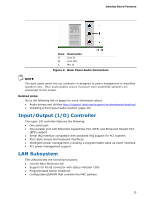
Desktop Board Features Hardware Support Power Connectors The Desktop Board has two power connectors. See Figure 12 on page 33 for the location of the power connectors. Fan Headers The Desktop Board has a 3-pin processor fan header and a 3-pin chassis fan header. See Figure 11 on page 32 for the location of the chassis fan header. The Desktop Board's standby power indicator, shown in Figure 4, is lit when there is standby power to the system. This includes the memory module and PCI bus connector, even when the computer appears to be off. If the system has a dual-colored power LED on the front panel, the sleep state is indicated by the LED turning amber. Figure 4. Location of the Standby Power Indicator Related Links: For more information on standby current requirements for the Desktop Board, refer to the Technical Product Specification by going to the following link, finding the product, and selecting Product Documentation from the left-hand menu: http://support.intel.com/support/motherboards/desktop/ 19
-
 1
1 -
2
-
3
-
4
-
5
-
6
-
7
-
8
-
9
-
10
-
11
-
12
-
13
-
 14
14 -
 15
15 -
 16
16 -
 17
17 -
 18
18 -
 19
19 -
 20
20 -
 21
21 -
 22
22 -
 23
23 -
 24
24 -
25
-
26
-
27
-
28
-
29
-
30
-
31
-
32
-
33
-
34
-
35
-
36
-
37
-
38
-
39
-
40
-
41
-
42
-
43
-
44
-
45
-
46
-
47
-
48
-
49
-
50
-
51
-
52
-
53
-
54
-
55
-
56
 |
 |
