Intel D845EBG2 Product Guide
Intel D845EBG2 - Desktop Board Motherboard Manual
 |
UPC - 735858153287
View all Intel D845EBG2 manuals
Add to My Manuals
Save this manual to your list of manuals |
Intel D845EBG2 manual content summary:
- Intel D845EBG2 | Product Guide - Page 1
Intel® Desktop Boards D845EPT2 and D845EBG2 Product Guide Order Number: A84611-001 - Intel D845EBG2 | Product Guide - Page 2
Intel® Desktop Boards D845EPT2 and D845EBG2 Product Guide. March 2002 If an FCC declaration of conformity marking is present on the board with the instructions, may cause Intel may make changes to specifications and product descriptions at any time, without notice. The Intel® Desktop Boards D845EPT2 - Intel D845EBG2 | Product Guide - Page 3
1 Desktop Board Features Desktop Board Components 9 Processor ...11 Main Memory ...12 Intel® 845E Chipset ...12 Intel® 82845E Memory Controller Hub (MCH 13 Intel® 82801DB I/O Controller Hub (ICH4 13 Firmware Hub (FWH 13 Input/Output (I/O) Controller 13 Audio Subsystem ...14 LAN Subsystem - Intel D845EBG2 | Product Guide - Page 4
the Front Panel Audio Solution 31 Clearing Passwords...32 Replacing the Battery ...33 3 Updating the BIOS Updating the BIOS with the Intel® Express BIOS Update Utility 37 Updating the BIOS with the Intel® Flash Memory Update Utility 38 Obtaining the BIOS Update File 38 Updating the BIOS...38 - Intel D845EBG2 | Product Guide - Page 5
a Memory Module 26 9. Removing the AGP Card 28 10. Connecting the IDE Cable 29 11. Location of the BIOS Configuration Jumper Block 30 12. Removing the Battery 35 13. Back Panel Connectors 62 14. Audio Connectors ...63 15. Power and Hardware Control Connectors 64 16. Desktop Board D845EPT2 Add - Intel D845EBG2 | Product Guide - Page 6
Intel Desktop Boards D845EPT2 and D845EBG2 Product Guide Tables 1. Feature Summary ...7 2. Processors Supported by the Desktop Boards D845EPT2 and D845EBG2 11 3. RJ-45 LAN Connector LEDs 14 4. Jumper Settings for the BIOS Setup Program Modes (J8H2 30 5. BIOS Setup Program Menu Bar 41 6. BIOS - Intel D845EBG2 | Product Guide - Page 7
Form Factors Processor Memory • microATX at 8.2 inches by 9.6 inches (Desktop Board D845EPT2) • ATX at 8.2 inches by 12.0 inches (Desktop Board D845EBG2) Support for a single Intel® Pentium® 4 processor with 533/400 MHz front side bus (FSB) frequency in an mPGA478 socket • Two 184-pin, 2.5 V SDRAM - Intel D845EBG2 | Product Guide - Page 8
values • WfM 2.0 compliant ✏ NOTE For information about Intel Desktop Boards D845EPT2 and D845EBG2, including the Technical Product Specification (TPS), BIOS updates, and device drivers, go to the Intel customer support World Wide Web site: http://support.intel.com/support/motherboards/desktop/ 8 - Intel D845EBG2 | Product Guide - Page 9
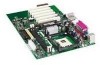
Z Front panel USB 2.0 header L Serial port B header AA Battery M Main power connector BB PCI bus add-in card connectors N Secondary IDE connector CC Communication and Networking Riser (CNR) (optional) O Primary IDE connector DD Front panel audio header Figure 1. Desktop Board D845EPT2 - Intel D845EBG2 | Product Guide - Page 10
connector (tachometer input) V Speaker H Intel 82845E Memory Controller Hub (MCH) W Front chassis fan connector I Processor socket X Front panel header J Processor fan connector (tachometer input) Y Alternate power/sleep LED header K DIMM sockets Z Front panel USB 2.0 header L Serial port - Intel D845EBG2 | Product Guide - Page 11
://support.intel.com/support/motherboards/desktop/ For instructions on installing or upgrading the processor, see Chapter 2 on page 21. The Desktop Boards D845EPT2 and D845EBG2 require an ATX12V compliant power supply to function according to Intel desktop board specifications. Both Desktop Boards - Intel D845EBG2 | Product Guide - Page 12
at: http://support.intel.com/support/motherboards/desktop/ All memory components and DIMMs used with the Intel desktop boards must comply with the PC SDRAM specifications. You can access these documents through the Internet at: http://www.intel.com/technology/memory/pcsdram/spec/ For information - Intel D845EBG2 | Product Guide - Page 13
Controller Hub (MCH) The MCH provides the processor, system memory, AGP, and hub interfaces in the Intel 845E chipset platform. Features on Desktop Boards D845EPT2 and D845EBG2 include: • Single processor support with 533/400 MHz data transfer rate • Designed to support up to 2 GB (with 512 Mbit - Intel D845EBG2 | Product Guide - Page 14
drivers, refer to the Desktop Board D845EPT2 or D845EBG2 link on Intel's World Wide Web site at: http://support.intel.com/support/motherboards/desktop RJ-45 LAN Connector LEDs Two LEDs are built into the RJ-45 LAN connector. Table 3 describes the LED states when the board is powered up and the LAN - Intel D845EBG2 | Product Guide - Page 15
a shielded cable that meets the requirements for a full-speed USB device. These Intel desktop boards support up to six USB 2.0 ports via ICH4; four ports routed to the back panel and two routed to a USB front panel header. USB 2.0 ports are backward compatible with USB 1.1 devices. USB 1.1 devices - Intel D845EBG2 | Product Guide - Page 16
interface that supports various features such as audio, modem, and LAN. BIOS The BIOS provides the Power-On Self-Test (POST), the BIOS Setup program, the PCI and IDE auto-configuration utilities. The BIOS is stored in the Firmware Hub. The BIOS can be updated by following the instructions in Chapter - Intel D845EBG2 | Product Guide - Page 17
the operating system direct control over the power management and Plug & Play functions of a computer. The use of ACPI with the Desktop Board D845EPT2 or D845EBG2 requires an operating system that provides full ACPI support. Suspend to RAM (Instantly Available PC Technology) CAUTION For Instantly - Intel D845EBG2 | Product Guide - Page 18
state. The Intel desktop board's standby power indicator, shown in Figure 3, is lit when there is standby power to the system. This includes the memory modules and PCI bus connectors, even when the computer appears to be off. If the system has a dual-colored power LED on the front panel, the sleep - Intel D845EBG2 | Product Guide - Page 19
• PME# wakeup support Power Connectors The Desktop Boards D845EPT2 and D845EBG2 have two power connectors. See Figure 15 on page 64 for the location of the power connectors. Fan Connectors The Desktop Boards D845EPT2 and D845EBG2 have two chassis fan connectors and one processor fan connector. See - Intel D845EBG2 | Product Guide - Page 20
during the Power-On Self-Test (POST). Battery A battery on the Intel desktop board keeps the values in CMOS RAM and the clock current when the computer is turned off. See Chapter 2 starting on page 21 for instructions on how to replace the battery. Real-Time Clock The Desktop Boards D845EPT2 and - Intel D845EBG2 | Product Guide - Page 21
desktop board • Install and remove a processor • Install and remove memory • Install and remove an AGP card • Connect the IDE cable • Set the BIOS jumper • Install the front panel audio electronic equipment. Disconnect the computer from its power source and from any telecommunications links, networks - Intel D845EBG2 | Product Guide - Page 22
Intel Desktop Boards D845EPT2 and D845EBG2 Product Guide Installing the I/O Shield The Desktop Boards D845EPT2 and D845EBG2 come with an I/O shield. When installed in the chassis, the shield blocks radio frequency transmissions, protects internal components from dust and foreign objects, - Intel D845EBG2 | Product Guide - Page 23
and Replacing Desktop Board Components Installing and Removing the Desktop Board Refer to your chassis manual for instructions on installing and removing the Intel desktop board. WARNING Only qualified technical personnel should do this procedure. Disconnect the computer from its power source before - Intel D845EBG2 | Product Guide - Page 24
Intel Desktop Boards D845EPT2 and D845EBG2 Product Guide Installing and Removing a Processor Instructions on how to install the processor to the Intel desktop board are given below. Installing a Processor CAUTION Before installing or removing the processor, make sure that AC power has been removed - Intel D845EBG2 | Product Guide - Page 25
Replacing Desktop Board Components Connecting the Processor Fan Heat Sink Cable Connect the processor fan heat sink cable to the processor fan connector (see Figure 7). OM13667 Figure 7. Connecting the Processor Fan Heat Sink Cable to the Processor Fan Connector Removing a Processor For instruction - Intel D845EBG2 | Product Guide - Page 26
memory specifications, the Intel desktop boards require DIMMs that support the Serial Presence Detect (SPD) data structure. You can access the PC Serial Presence Detect Specification at: http://www.intel.com/technology/memory/pcsdram/spec/ The Desktop Boards D845EPT2 and D845EBG2 have two 184-pin - Intel D845EBG2 | Product Guide - Page 27
's cover and reconnect the AC power cord. Installing and Removing the AGP Card The AGP connector supports 1.5 V 4X and 2X AGP cards. The Desktop Boards D845EPT2 and D845EBG2 have an integrated AGP retention mechanism (RM). Installing an AGP Card Follow these instructions to install an AGP card - Intel D845EBG2 | Product Guide - Page 28
Intel Desktop Boards D845EPT2 and D845EBG2 Product Guide Removing the AGP Card Follow these instructions to remove the AGP card from the RM: 1. Remove the screw (B) that secures the card's metal bracket (A) to the chassis back panel. 2. Push back on the RM lever (D), as shown in Figure 9, until the - Intel D845EBG2 | Product Guide - Page 29
as a slave to an ATAPI CD-ROM drive. For correct function of the cable: • Attach the cable end with the single connector to the Intel desktop board (see Figure 10, A). • Attach the cable end with the two closely spaced connectors to the drives (see Figure 10, B). B A Figure 10. Connecting the IDE - Intel D845EBG2 | Product Guide - Page 30
Intel Desktop Boards D845EPT2 and D845EBG2 Product Guide Setting the BIOS Configuration Jumper Block CAUTION Always turn off the power and unplug the power cord from the computer before changing the jumper. Moving the jumper with the power on may result in unreliable computer operation. The location - Intel D845EBG2 | Product Guide - Page 31
Installing and Replacing Desktop Board Components Installing the Front Panel Audio Solution To install the cable that connects the front panel audio solution to the front panel audio header, follow these steps: 1. Observe the precautions in "Before You Begin" on page 21. 2. Turn off all peripheral - Intel D845EBG2 | Product Guide - Page 32
Intel Desktop Boards D845EPT2 and D845EBG2 Product Guide Clearing Passwords This procedure assumes that the Intel desktop board is Disconnect the computer's power cord from the AC power source. 11. Remove the computer cover. 12. To restore normal operation, place the jumper on pins 1-2 as shown - Intel D845EBG2 | Product Guide - Page 33
Installing and Replacing Desktop Board Components Replacing the Battery A coin-cell battery (CR2032) powers the real-time clock and CMOS memory. When the computer is not plugged into a wall socket, the battery has an estimated life of three years. When the computer is plugged in, the - Intel D845EBG2 | Product Guide - Page 34
Intel Desktop Boards D845EPT2 and D845EBG2 Product Guide VORSICHT Bei falschem Einsetzen einer neuen Batterie besteht Explosionsgefahr. Die Batterie darf nur durch denselben oder einen entsprechenden, vom Hersteller empfohlenen Batterietyp ersetzt werden. Entsorgen - Intel D845EBG2 | Product Guide - Page 35
and Replacing Desktop Board Components To replace the battery, follow these steps: 1. Observe the precautions in "Before You Begin" (see page 21). 2. Turn off all peripheral devices connected to the computer. Disconnect the computer's power cord from the AC power source (wall outlet or power adapter - Intel D845EBG2 | Product Guide - Page 36
Intel Desktop Boards D845EPT2 and D845EBG2 Product Guide 36 - Intel D845EBG2 | Product Guide - Page 37
Intel Express BIOS Update utility: 1. Go to the Intel customer support World Wide Web site: http://support.intel.com/support/motherboards/desktop/ 2. Navigate to the D845EPT2 or D845EBG2 page and click the Express BIOS Update utility file for the Desktop Board D845EPT2 or D845EBG2 BIOS. 3. Download - Intel D845EBG2 | Product Guide - Page 38
D845EPT2 or D845EBG2 page on the Intel customer support World Wide Web site: http://support.intel.com/support/motherboards/desktop ✏ NOTE Please review the instructions distributed with the update utility before attempting a BIOS update. The Intel Flash Memory Update Utility allows you to: • Update - Intel D845EBG2 | Product Guide - Page 39
jumper block (J8H2) (see Figure 11). 3. Remove the jumper from all pins as shown below to set recovery mode for Setup. 31 4. Insert the bootable BIOS update diskette into floppy drive A. 5. Replace the computer cover, connect the power cord, turn on the computer, and allow it to boot. The recovery - Intel D845EBG2 | Product Guide - Page 40
Intel Desktop Boards D845EPT2 and D845EBG2 Product Guide 40 - Intel D845EBG2 | Product Guide - Page 41
may not show the latest settings. For the latest BIOS settings, refer to the Intel Desktop Board D845EPT2/D845EBG2 Technical Product Specification or the Intel customer support World Wide Web site: http://support.intel.com/support/motherboards/desktop ✏ NOTE For reference purposes, you should write - Intel D845EBG2 | Product Guide - Page 42
Intel Desktop Boards D845EPT2 and D845EBG2 Product Guide Table 6 shows the function keys available for menu screens. Table 6. BIOS Setup Program Function Keys BIOS Setup Program Function Key or or Description Selects a different menu screen Moves cursor up - Intel D845EBG2 | Product Guide - Page 43
. Cache lookups are not performed. Both the video driver and the application must support Write Combining. Selects UnCacheable (UC) video memory cache mode. This setting identifies the video memory range as uncacheable by the processor. Memory writes are performed in program order. Cache lookups are - Intel D845EBG2 | Product Guide - Page 44
Intel Desktop Boards D845EPT2 and D845EBG2 Product Guide Main Menu Maintenance Main Advanced Security Power Boot Exit Table 9 describes the Main Menu. This menu reports processor and memory information and is used to configure the system date and system time. Table 9. Main Menu Feature - Intel D845EBG2 | Product Guide - Page 45
Using the Setup Program Advanced Menu Maintenance Main Advanced Security Power Boot Exit PCI Configuration Boot Configuration Peripheral Configuration IDE Configuration Floppy Configuration Event Log Configuration Video Configuration USB Configuration Table 10 describes the Advanced - Intel D845EBG2 | Product Guide - Page 46
Intel Desktop Boards D845EPT2 and D845EBG2 Product Guide PCI Configuration Submenu Maintenance Main Advanced Security Power Boot Exit PCI Configuration Boot Configuration Peripheral Configuration IDE Configuration Floppy Configuration Event Log Configuration Video Configuration USB - Intel D845EBG2 | Product Guide - Page 47
to set the Plug & Play options, reset configuration data, and the power-on state of the Numlock key. Table 12. Boot Configuration Submenu Feature O/S • No (default) • Yes Specifies if manual configuration is desired. No lets the BIOS configure all devices. This setting is appropriate when using - Intel D845EBG2 | Product Guide - Page 48
Intel Desktop Boards D845EPT2 and D845EBG2 Product Guide Peripheral Configuration Submenu Maintenance Main Advanced Security Power Boot Exit PCI Configuration Boot Configuration Peripheral Configuration IDE Configuration Floppy Configuration Event Log Configuration Video Configuration - Intel D845EBG2 | Product Guide - Page 49
Enabled) DMA Channel (This feature is present only when Parallel Port Mode is set to ECP) Audio Device LAN Device (This feature is present only when there is onboard LAN) Options • Disabled • Enabled • Auto (default) • Output Only • Bi-directional (default) • EPP • ECP • 378 (default) • 278 • IRQ - Intel D845EBG2 | Product Guide - Page 50
Intel Desktop Boards D845EPT2 and D845EBG2 Product Guide IDE Configuration Submenu Maintenance Main Advanced Security Power Boot Exit PCI Configuration Boot Configuration Peripheral Configuration IDE Configuration Floppy Configuration Event Log Configuration Video Configuration USB - Intel D845EBG2 | Product Guide - Page 51
Main Advanced Security Boot Configuration Peripheral Configuration IDE Configuration Floppy Configuration Event Log Configuration Video Configuration USB Configuration Power Boot Exit ➜ Primary IDE Master Primary IDE Slave Secondary IDE Master Secondary IDE Slave There are four IDE - Intel D845EBG2 | Product Guide - Page 52
Intel Desktop Boards D845EPT2 and D845EBG2 Product Guide Table 15. Primary/Secondary IDE Master/Slave Submenus (continued) Feature DMA Mode ARMD : Ultra DMA. Select ARMD device emulation type by BIOS. Note: These configuration options appear only if an IDE Advanced Security Power Boot Exit - Intel D845EBG2 | Product Guide - Page 53
Using the Setup Program Event Log Configuration Submenu Maintenance Main Advanced Security Power Boot Exit PCI Configuration Boot Configuration Peripheral Configuration IDE Configuration Floppy Configuration Event Log Configuration Video Configuration USB Configuration The submenu - Intel D845EBG2 | Product Guide - Page 54
Intel Desktop Boards D845EPT2 and D845EBG2 Product Guide Video Configuration Submenu Maintenance Main Advanced Security Power default) • 128MB • 256MB • AGP (default) • PCI Description Amount of system memory available for direct access by the AGP device. Selects primary video adapter to be - Intel D845EBG2 | Product Guide - Page 55
a USB 2.0 driver is not available. Enables USB legacy support. Security Menu Maintenance Main Advanced Security Power Boot Exit The supervisor password. Specifies the user password. Clears the user password. Sets BIOS Setup Utility access rights for user level. Notes: 1. This feature - Intel D845EBG2 | Product Guide - Page 56
Intel Desktop Boards D845EPT2 and D845EBG2 Product Guide Power Menu Maintenance Main Advanced Security Power Boot Exit The menu shown in Table 21 is used to set power management features. Table 21. Power Menu Feature ACPI After Power Failure Wake on PME Wake on Modem Ring Options No - Intel D845EBG2 | Product Guide - Page 57
Power Boot Exit The menu shown in Table 23 is used to set the boot features and the boot sequence. Table 23. Boot Menu Feature Quiet Boot Intel Rapid BIOS (default) POST tests. • Disabled (default) Enables the BIOS to scan the flash memory for user binary • Enabled files that are executed at - Intel D845EBG2 | Product Guide - Page 58
Intel Desktop Boards D845EPT2 and D845EBG2 Product Guide Boot Device Priority Submenu Maintenance Main Advanced Security Power Boot Exit the first through final boot devices are, respectively listed below. The BIOS supports up to sixteen total boot devices in any combination of the boot - Intel D845EBG2 | Product Guide - Page 59
. This list will display up to twelve hard disk drives, the maximum number of hard disk drives supported by the BIOS. Removable Devices Submenu Maintenance Main Advanced Security Power The submenu in shown Table 26 is for setting removable devices. Boot Exit Boot Device Priority Hard Disk - Intel D845EBG2 | Product Guide - Page 60
Intel Desktop Boards D845EPT2 and D845EBG2 Product Guide ATAPI CD-ROM Drives Maintenance Main Advanced Security Power Boot -ROM drives supported by the BIOS. Exit Menu Maintenance Main Advanced Security Power Boot Exit The menu shown in Table 28 is used to exit the BIOS Setup program, - Intel D845EBG2 | Product Guide - Page 61
The Intel desktop board connectors can be divided into three groups: • Back panel connectors • Midboard connectors - Audio connectors - Power and hardware connectors - Add-in board and peripheral interface connectors • Front panel headers CAUTION Many of the midboard and front panel connectors - Intel D845EBG2 | Product Guide - Page 62
Intel Desktop Boards D845EPT2 and D845EBG2 Product Guide Back Panel Connectors Figure 13 shows the back panel connectors. A E G C BD F H I J Panel Connectors ✏ NOTE The line out connector, located on the back panel, is designed to power either headphones or amplified speakers only. Poor audio - Intel D845EBG2 | Product Guide - Page 63
Reference Item A B C Description Front panel audio (see Table 29 for pin assignments) Auxiliary line in CD-ROM Figure 14. Audio Connectors Table 29 shows the pin assignments for the front panel audio header. Table 29. Front Panel Audio Header Signal Names (J8B1) Pin Signal Name 1 AUD-MIC - Intel D845EBG2 | Product Guide - Page 64
Desktop Boards D845EPT2 and D845EBG2 require an ATX12V compliant power supply to function according to Desktop Board specifications. Both Intel desktop boards have two ATX12V compliant power supply connectors that are needed to provide extra power to the Intel 845E chipset and Pentium 4 processor - Intel D845EBG2 | Product Guide - Page 65
Add-In Card and Peripheral Interface Connectors Figure 16 shows the add-in card and peripheral interface connectors for the Desktop Board D845EPT2. A B C DE 2 1 2 1 1 2 1 40 39 40 39 34 33 I H G Item A B C D E Description CNR (optional) PCI bus connector 3 PCI bus connector 2 PCI bus - Intel D845EBG2 | Product Guide - Page 66
Intel Desktop Boards D845EPT2 and D845EBG2 Product Guide Figure 17 shows the add-in card and peripheral interface connectors for the Desktop Board D845EBG2. A B C D E F GH 2 1 2 1 1 2 1 40 39 40 39 34 33 L K JI OM13657 Item A B C D E F Description CNR (optional) PCI bus connector 6 PCI - Intel D845EBG2 | Product Guide - Page 67
Description Front panel audio (see Table 29 on page 63 for pin assignments) Front panel USB 2.0 (see Table 30 for pin assignments) Front panel Alternate power/sleep LED Figure 18. Front Panel Headers Table 30 shows the pin assignments for the front panel USB 2.0 header. Table 30. Front Panel USB - Intel D845EBG2 | Product Guide - Page 68
Intel Desktop Boards D845EPT2 and D845EBG2 Product Guide Desktop Board Resources Memory Map Table 31. System Memory Map Address Range (decimal) Address Range (hex) 1024 K - 2097152 K 100000 - 7FFFFFF 960 K - 1024 K F0000 - FFFFF 896 K - 960 K E0000 - EFFFF 800 K - 896 K C8000 - DFFFF - Intel D845EBG2 | Product Guide - Page 69
Interrupts Table 33. Interrupts IRQ System Resource NMI I/O channel check 0 Reserved, interval timer 1 Reserved, keyboard buffer full 2 Reserved, cascade interrupt from slave PIC 3 COM2* 4 COM1* 5 LPT2 (Plug and Play option) / ** 6 Floppy drive controller 7 LPT1* 8 Real time - Intel D845EBG2 | Product Guide - Page 70
Intel Desktop Boards D845EPT2 and D845EBG2 Product Guide 70 - Intel D845EBG2 | Product Guide - Page 71
A Error Messages and Indicators The Desktop Boards D845EPT2 and D845EBG2 report POST errors in two ways: • By sounding a beep code • By displaying an error message on the monitor BIOS Beep Codes The BIOS beep codes are listed in Table 34. The BIOS also issues a beep code (one long tone followed by - Intel D845EBG2 | Product Guide - Page 72
Desktop Boards D845EPT2 and D845EBG2 Product Guide BIOS Error Messages When a recoverable error occurs during the POST, the BIOS displays an error message describing the problem. Table 35. BIOS Error Messages Error Message Explanation GA20 Error An error occurred with Gate-A20 when switching - Intel D845EBG2 | Product Guide - Page 73
. BIOS Error Messages (continued) Error Message Explanation Memory Size Decreased Memory size has decreased since the last boot. If no memory was removed, then memory may be bad. Memory Size Increased Memory size has increased since the last boot. If no memory was added, there may be a problem - Intel D845EBG2 | Product Guide - Page 74
Intel Desktop Boards D845EPT2 and D845EBG2 Product Guide 74 - Intel D845EBG2 | Product Guide - Page 75
regulations, and product certification markings for the Desktop Boards D845EPT2 and D845EBG2. • Instructions and precautions for integrators who are installing the Intel desktop board in a chassis. Safety Regulations The Desktop Boards D845EPT2 and D845EBG2 comply with the safety regulations stated - Intel D845EBG2 | Product Guide - Page 76
Intel Desktop Boards D845EPT2 and D845EBG2 Product Guide Product Certification Markings The Desktop Boards D845EPT2 and D845EBG2 have the following product certification markings: • UL joint US/Canada Recognized Component mark: consists of small c followed by a stylized backward UR and followed - Intel D845EBG2 | Product Guide - Page 77
Intel desktop board, observe all warnings and cautions in the installation instructions. To avoid injury, be careful of: • Sharp pins on connectors • Sharp pins on printed circuit assemblies • Rough edges and sharp corners on the chassis • Hot components (like processors If the power supply and - Intel D845EBG2 | Product Guide - Page 78
Intel Desktop Boards D845EPT2 and D845EBG2 Product Guide Chassis and Component Certifications Ensure that the chassis and certain components; such as the power at the front of this product guide demonstrates compliance instructions. Use Only for Intended Applications All Intel desktop processor boards
-
 1
1 -
 2
2 -
 3
3 -
 4
4 -
 5
5 -
 6
6 -
 7
7 -
8
-
9
-
10
-
11
-
12
-
13
-
14
-
15
-
16
-
17
-
18
-
19
-
20
-
21
-
22
-
23
-
24
-
25
-
26
-
27
-
28
-
29
-
30
-
31
-
32
-
33
-
34
-
35
-
36
-
37
-
38
-
39
-
40
-
41
-
42
-
43
-
44
-
45
-
46
-
47
-
48
-
49
-
50
-
51
-
52
-
53
-
54
-
55
-
56
-
57
-
58
-
59
-
60
-
61
-
62
-
63
-
64
-
65
-
66
-
67
-
68
-
69
-
70
-
71
-
72
-
73
-
74
-
75
-
76
-
77
-
78
 |
 |

Intel
®
Desktop Boards
D845EPT2 and D845EBG2
Product Guide
Order Number:
A84611-001