Intel D845EBG2 Product Guide - Page 64
Power and Hardware Connectors
 |
UPC - 735858153287
View all Intel D845EBG2 manuals
Add to My Manuals
Save this manual to your list of manuals |
Page 64 highlights
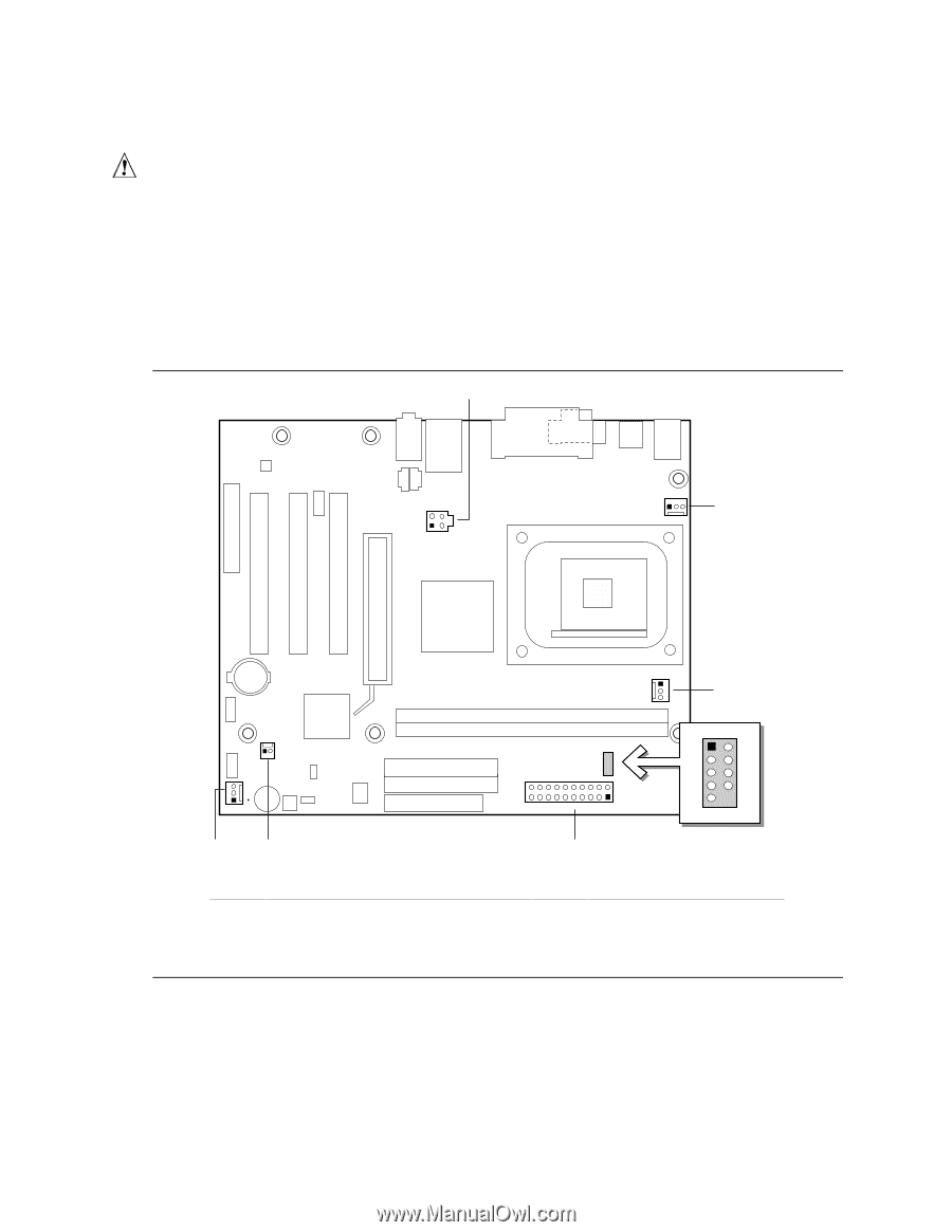
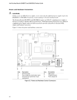
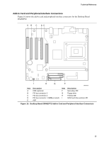
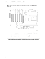
Intel Desktop Boards D845EPT2 and D845EBG2 Product Guide Power and Hardware Connectors CAUTION Failure to use an ATX12V power supply, or not connecting the additional power supply lead to the D845EPT2 or D845EBG2 board may result in damage to the Intel desktop board. The Desktop Boards D845EPT2 and D845EBG2 require an ATX12V compliant power supply to function according to Desktop Board specifications. Both Intel desktop boards have two ATX12V compliant power supply connectors that are needed to provide extra power to the Intel 845E chipset and Pentium 4 processor. Figure 15 shows the power and hardware connectors. A 2 4 1 3 1 B 1 C 1 1 1 2 3 4 20 11 5 7 6 8 D 10 1 9 G F E Item A B C D Description ATX12V power Rear chassis fan (tachometer input) Processor fan (tachometer input) Serial port B Item E F G Description Main power Chassis intrusion Front chassis fan Figure 15. Power and Hardware Control Connectors OM13660 64
-
 1
1 -
2
-
3
-
4
-
5
-
6
-
7
-
8
-
9
-
10
-
11
-
12
-
13
-
14
-
15
-
16
-
17
-
18
-
19
-
20
-
21
-
22
-
23
-
24
-
25
-
26
-
27
-
28
-
29
-
30
-
31
-
32
-
33
-
34
-
35
-
36
-
37
-
38
-
39
-
40
-
41
-
42
-
43
-
44
-
45
-
46
-
47
-
48
-
49
-
50
-
51
-
52
-
53
-
54
-
55
-
56
-
57
-
58
-
 59
59 -
 60
60 -
 61
61 -
 62
62 -
 63
63 -
 64
64 -
 65
65 -
 66
66 -
 67
67 -
 68
68 -
 69
69 -
70
-
71
-
72
-
73
-
74
-
75
-
76
-
77
-
78
 |
 |