Intel D845GLVA Intel Desktop Board D845GLVA Product Guide English. - Page 57
Midboard Connectors, Audio
 |
View all Intel D845GLVA manuals
Add to My Manuals
Save this manual to your list of manuals |
Page 57 highlights
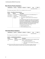
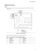
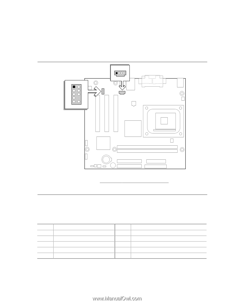
Technical Reference Midboard Connectors Audio Figure 12 shows the location of the front panel audio header (A) and ATAPI-style CD-ROM connector (B). B 14 1 2 3 4 A5 6 7 9 10 Item A B Description Front panel audio CD-ROM (Atapi-style) Figure 12. Audio Connectors Table 29 shows the pin assignments for the front panel audio header. Table 29. Front Panel Audio Header Signal Names (J8A1) Pin Signal Name 1 AUD-MIC 3 AUD-MIC-BIAS 5 AUD-FPOUT-R 7 HP-ON 9 AUD-FPOUT-L Pin Signal Name 2 AUD-GND 4 AUD-VCC 6 AUD-RET-R 8 KEY 10 AUD-RET-L OM15865 57
-
 1
1 -
2
-
3
-
4
-
5
-
6
-
7
-
8
-
9
-
10
-
11
-
12
-
13
-
14
-
15
-
16
-
17
-
18
-
19
-
20
-
21
-
22
-
23
-
24
-
25
-
26
-
27
-
28
-
29
-
30
-
31
-
32
-
33
-
34
-
35
-
36
-
37
-
38
-
39
-
40
-
41
-
42
-
43
-
44
-
45
-
46
-
47
-
48
-
49
-
50
-
51
-
 52
52 -
 53
53 -
 54
54 -
 55
55 -
 56
56 -
 57
57 -
 58
58 -
 59
59 -
 60
60 -
 61
61 -
 62
62 -
63
-
64
-
65
-
66
-
67
-
68
-
69
-
70
-
71
-
72
 |
 |
Technical Reference
57
Midboard Connectors
Audio
Figure 12 shows the location of the front panel audio header (A) and ATAPI-style CD-ROM
connector (B).
OM15865
B
1
3
5
7
9
2
4
6
10
A
1
4
Item
Description
A
Front panel audio
B
CD-ROM (Atapi-style)
Figure 12.
Audio Connectors
Table 29 shows the pin assignments for the front panel audio header.
Table 29.
Front Panel Audio Header Signal Names (J8A1)
Pin
Signal Name
Pin
Signal Name
1
AUD-MIC
2
AUD-GND
3
AUD-MIC-BIAS
4
AUD-VCC
5
AUD-FPOUT-R
6
AUD-RET-R
7
HP-ON
8
KEY
9
AUD-FPOUT-L
10
AUD-RET-L