Intel D850EMV2 Product Specification
Intel D850EMV2 Manual
 |
View all Intel D850EMV2 manuals
Add to My Manuals
Save this manual to your list of manuals |
Intel D850EMV2 manual content summary:
- Intel D850EMV2 | Product Specification - Page 1
® Desktop Board D850EMD2/D850EMV2 Technical Product Specification April 2002 Order Number: A94395-001 The Intel® Desktop Boards D850EMD2/D850EMV2 may contain design defects or errors known as errata that may cause the product to deviate from published specifications. Current characterized - Intel D850EMV2 | Product Specification - Page 2
4725, Europe 44-0-1793-431-155, France 44-0-1793-421-777, Germany 44-0-1793-421-333, other Countries 708-296-9333. Intel and Pentium are registered trademarks of Intel Corporation or its subsidiaries in the United States and other countries. † Other names and brands may be claimed as the property of - Intel D850EMV2 | Product Specification - Page 3
power and environmental requirements, and the BIOS for these Intel desktop boards: D850EMD2 and D850EMV2. It describes the standard D850EMD2 and D850EMV2 A map of the resources of the desktop boards The features supported by the BIOS Setup program The contents of the BIOS Setup program's menus and - Intel D850EMV2 | Product Specification - Page 4
Intel Desktop Board D850EMD2/D850EMV2 Technical Product Specification Other Common Notation # (NxnX) GB GB/sec KB Kbit kbits/sec MB MB/sec Mbit Mbit/sec xxh x.x V † - Intel D850EMV2 | Product Specification - Page 5
18 1.4 Operating System Support 18 1.5 Design Specifications 19 1.6 Processor ...22 1.7 System Memory ...23 1.7.1 Memory Features 23 1.7.2 Continuity RIMM Modules 23 1.7.3 RDRAM Memory Configuration 24 1.8 Intel® 850E Chipset ...25 1.8.1 AGP ...26 1.8.2 USB...26 1.8.3 IDE Support 28 1.8.4 Real - Intel D850EMV2 | Product Specification - Page 6
Intel Desktop Board D850EMD2/D850EMV2 Technical Product Specification 2 Technical Reference 2.1 Introduction...47 2.2 Memory PCI Autoconfiguration 87 3.3.2 PCI IDE Support 88 3.4 SMBIOS ...88 3.5 Legacy USB Support 89 3.6 BIOS Updates ...89 3.6.1 Language Support 90 3.6.2 Custom Splash Screen - Intel D850EMV2 | Product Specification - Page 7
Attached Devices 92 3.8.4 Changing the Default Boot Device During POST 92 3.9 Fast Booting Systems with Intel® Rapid BIOS Boot 92 3.9.1 Peripheral Selection and Configuration 92 3.9.2 Intel Rapid BIOS Boot 93 3.9.3 Operating System 93 3.10 BIOS Security Features 93 4 BIOS Setup Program - Intel D850EMV2 | Product Specification - Page 8
Block Diagram 16 4. Block Diagram with Optional USB 2.0 Support 17 5. Intel 850E Chipset Block Diagram 25 6. USB 1.1 Port Configuration 4. Specifications ...19 5. Supported Processors 22 6. Supported Memory Configurations 24 7. Memory Support Matrix 24 8. Supported IDE Modes 28 9. LAN - Intel D850EMV2 | Product Specification - Page 9
. ATAPI CD-ROM Connector 59 31. Fan 3 Connector (Desktop Board D850EMV2 Only 61 32. Chassis Intrusion Connector 61 33. ATX12V Power Connector 61 34. Processor Fan Connector 61 35. Fan 1 Connector...62 36. Main Power Connector 62 37. Fan 2 Connector...62 38. CNR Connector (Optional 65 39. PCI - Intel D850EMV2 | Product Specification - Page 10
Intel Desktop Board D850EMD2/D850EMV2 Technical Product Specification 69. Boot Configuration Submenu 101 70. Peripheral Configuration Submenu 102 71. IDE Configuration Submenu 104 72. Primary/Secondary - Intel D850EMV2 | Product Specification - Page 11
What This Chapter Contains 1.1 Board Differences...11 1.2 Overview ...12 1.3 Online Support ...18 1.4 Operating System Support 18 1.5 Design Specifications 19 1.6 Processor ...22 1.7 System Memory ...23 1.8 Intel® 850E Chipset ...25 1.9 I/O Controller ...30 1.10 Audio Subsystem...32 1.11 - Intel D850EMV2 | Product Specification - Page 12
Wake Capabilities Desktop Board D850EMD2: microATX (9.60 inches by 9.60 inches) Desktop Board D850EMV2: ATX (12.00 inches by 9.60 inches) • Support for an Intel® Pentium® 4 processor in a µPGA478 socket • 400/533 MHz system data bus • Two Direct-RDRAM channels with two RIMM†s per channel (four RIMM - Intel D850EMV2 | Product Specification - Page 13
available in all marketing channels. Please contact your Intel representative to determine which manufacturing options are available with PCI bus connector 6 on the desktop board D850EMV2) Support for USB 2.0 devices. The USB 2.0 option supports up to five USB ports. It uses the following components - Intel D850EMV2 | Product Specification - Page 14
82562ET PLC device (optional) C AGP connector D Back panel connectors E +12 V power connector (ATX12V) F Intel 82850E MCH G µPGA478 processor socket H Hardware monitor I RAMBUS† Bank 0 (RIMM1 and RIMM2) J RAMBUS Bank 1 (RIMM3 and RIMM4) K Power connector L Diskette drive connector M IDE connectors - Intel D850EMV2 | Product Specification - Page 15
PLC device (optional) C AGP connector D Back panel connectors E +12 V power connector (ATX12V) F Intel 82850E MCH G µPGA478 processor socket H Hardware monitor I RAMBUS Bank 0 (RIMM1 and RIMM2) J RAMBUS Bank 1 (RIMM3 and RIMM4) K Power connector N M L K OM14441 L Diskette drive connector - Intel D850EMV2 | Product Specification - Page 16
Intel Desktop Board D850EMD2/D850EMV2 Technical Product Specification 1.2.4 Block Diagram Figure 3 is a block diagram of the major functional areas of the standard desktop boards D850EMD2/D850EMV2. See Figure 6 on page 27 for USB port routing. Primary/ Secondary IDE ATA-66/100 µPGA478 Processor - Intel D850EMV2 | Product Specification - Page 17
Figure 7 on page 28 for USB port routing. Primary/ Secondary IDE ATA-66/100 µPGA478 Processor Socket System Bus (400/533 MHz) 850E Chipset AGP Interface 4X AGP Connector (1.5 V only) Panel USB Ports (2) = connector or socket Figure 4. Block Diagram with Optional USB 2.0 Support OM14438 17 - Intel D850EMV2 | Product Specification - Page 18
boards 850EMD2/D850EMV2 Processor data sheets ICH2 addressing Custom splash screens Audio software and utilities LAN software and drivers Visit this World Wide Web site: http://www.intel.com/design/motherbd http://support.intel.com/support/motherboards/desktop http://www.intel.com/design/litcentr - Intel D850EMV2 | Product Specification - Page 19
Design Guide Boot Integrity Services (BIS) Application Programming Interface (API) Communication and Network Riser (CNR) Specification Enhanced Host Controller Interface Specification for Universal Serial Bus Version, Revision Date, and Ownership Revision 2.2, September 2000, Intel Corporation - Intel D850EMV2 | Product Specification - Page 20
May 5, 1994, Compaq Computer Corp., Phoenix Technologies Ltd., and Intel Corporation. Version 2.1, September 1999, Intel Corporation. Version 1.0, March 1999, Rambus Corporation. Version 1.0, February 1999, Rambus Corporation. The information is available from... http://standards.ieee.org/ reading - Intel D850EMV2 | Product Specification - Page 21
Guide Universal Serial Bus Specification Wired for Management Baseline Version, Revision Date and Ownership Version 2.3.1, March 16, 1999, American Megatrends Inc., Award Software International Inc., Compaq Computer Corporation, Dell Computer Corporation, Hewlett-Packard Company, Intel Corporation - Intel D850EMV2 | Product Specification - Page 22
Type Pentium 4 processor Pentium 4 processor Pentium 4 processor Designation Up to 2.4 GHz Up to 2.4A GHz Up to 2.53 GHz System Bus 400 MHz 400 MHz 533 MHz L2 Cache Size 256 KB 512 KB 512 KB The list of supported processors for the desktop boards D850EMD2/D850EMV2 is available from Intel's World - Intel D850EMV2 | Product Specification - Page 23
the standby power indicator LED.) ✏ NOTE The desktop boards D850EMD2/D850EMV2 support combinations of no more than 32 RDRAM components per RDRAM bank. If 82850E MCH integrates two lock-stepped Direct Rambus banks, providing a processor-tomemory bandwidth up to 3.2 GB/sec. The desktop boards D850EMD2 - Intel D850EMV2 | Product Specification - Page 24
Intel Desktop Board D850EMD2/D850EMV2 Technical Product Specification 1.7.3 RDRAM Memory lists the supported combinations of memory types with processor system bus values. Table 7. Memory Support Matrix Processor System Bus 533 MHz 400 MHz Support for PC800-40 memory? Yes Yes Support for PC800 - Intel D850EMV2 | Product Specification - Page 25
82850E MCH with Accelerated Hub Architecture (AHA) bus • Intel 82801BA ICH2 with AHA bus • 4 Mbit FWH The Hub (FWH) Dual RAMBUS AGP Channels Interface LPC Bus SMBus PCI Bus AC Link Figure 5. Intel 850E Chipset Block Diagram OM14439 ✏ NOTE The USB bus is routed from the NEC USB 2.0 controller - Intel D850EMV2 | Product Specification - Page 26
Intel Desktop Board D850EMD2/D850EMV2 Technical Product Specification 1.8.1 AGP ✏ NOTE The AGP connector is keyed for 1.5 V AGP cards only. Do not attempt to install a legacy 3.3 V AGP card. The AGP connector is not mechanically compatible with legacy 3.3 V AGP cards. The AGP connector supports - Intel D850EMV2 | Product Specification - Page 27
external hub can be connected to any of the ports. Boards with the USB 2.0 option fully support OHCI and EHCI and use OHCI- and EHCI-compatible drivers. ✏ NOTE USB 2.0 support has been tested with Windows 2000 and Windows XP drivers and is not currently supported by any other operating system. 27 - Intel D850EMV2 | Product Specification - Page 28
Intel Desktop Board D850EMD2/D850EMV2 Technical Product Specification NEC µPD720100 PCI USB the processor • DMA protocol on the IDE bus • Supports host and target throttling • DMA protocol on the IDE bus • Allows host and target throttling • Similar to Ultra DMA • Device driver compatible - Intel D850EMV2 | Product Specification - Page 29
Product Description ✏ NOTE The BIOS will always recognize an LS-120 drive as an ATAPI floppy drive. To ensure correct operation, do not configure the drive as a hard disk drive. For information about The location of the IDE connectors The signal names of the IDE connectors The Boot menu in the - Intel D850EMV2 | Product Specification - Page 30
Intel Desktop Board D850EMD2/D850EMV2 Technical Product Specification 1.9 I/O Controller The SMSC LPC47M142 I/O controller provides the following features: • 3.3 V operation • Two serial ports • One parallel port with Extended Capabilities Port (ECP) and Enhanced Parallel Port (EPP) support • - Intel D850EMV2 | Product Specification - Page 31
diskette drive interface. For information about The location of the diskette drive connector The signal names of the diskette drive connector The supported diskette drive capacities and sizes Refer to Section 2.8.2.4, page 63 Table 41, page 68 Table 73, page 107 1.9.4 Keyboard and Mouse Interface - Intel D850EMV2 | Product Specification - Page 32
of the following devices: • Intel 82801BA ICH2 • Analog Devices AD1885 analog codec The audio subsystem includes these features: • Split digital/analog architecture for improved signal-to-noise (S/N) ratio: ≥ 85 dB • Power management support for ACPI 1.0 (driver dependant) • 3-D stereo enhancement - Intel D850EMV2 | Product Specification - Page 33
signal names of the ATAPI CD-ROM connector Refer to Figure 13, page 58 Table 30, page 59 1.10.2 Audio Subsystem Software Audio software and drivers are available from Intel's World Wide Web site. For information about Obtaining audio software and - Intel D850EMV2 | Product Specification - Page 34
through the CNR connector. The Intel 82562ET provides the following functions: • Basic 10/100 Ethernet LAN connectivity • RJ-45 connector support with status indicator LEDs on the back panel • Full device driver compatibility • ACPI support • Programmable transit threshold • Configuration EEPROM - Intel D850EMV2 | Product Specification - Page 35
Wide Web site. For information about Obtaining LAN software and drivers Refer to Section 1.3, page 18 1.12 CNR (Optional) The CNR connector provides an interface that supports the audio, modem, USB, and LAN interfaces of the Intel 850E chipset. Figure 9 shows the signal interface between the - Intel D850EMV2 | Product Specification - Page 36
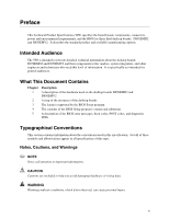
your Intel desktop board. 1.13.1.1 Hardware Monitoring ASIC The features of the hardware monitoring ASIC (Analog Devices ADM1025, Philips Semiconductor NE1619, or equivalent) include: • Internal ambient temperature sensor • Remote thermal diode sensor for direct monitoring of processor temperature - Intel D850EMV2 | Product Specification - Page 37
SMSC EMC6D101, or equivalent) include: • Internal ambient temperature sensor • Two remote thermal diode sensors for direct monitoring of processor temperature and ambient temperature sensing • Power supply monitoring of five voltages (+5 V, +12 V, +3.3 V, +1.5 V, and +VCCP1) to detect levels above - Intel D850EMV2 | Product Specification - Page 38
Intel Desktop Board D850EMD2/D850EMV2 Technical Product Specification E D A B C G F Item A B C D E F G Note: OM14480 Description Thermal diode, located on processor die Ambient temperature sensor, internal to both hardware monitoring ASIC options Remote ambient temperature sensor (Note) - Intel D850EMV2 | Product Specification - Page 39
desktop boards D850EMD2/D850EMV2 requires an operating system that provides full ACPI support. ACPI features include: • Plug and Play (including bus and device add-in boards (some add-in boards may require an ACPI-aware driver), video displays, and hard disk drives. • Methods for achieving less than - Intel D850EMV2 | Product Specification - Page 40
Intel Table 11 lists the power states supported by the desktop boards D850EMD2/D850EMV2 S5 - Soft-off. Context not saved. Cold boot is required. Processor States C0 - working C1 - stop grant No power No power No source No power to the system so that service can be performed Notes: 1. Total system - Intel D850EMV2 | Product Specification - Page 41
The use of these wake-up events from an ACPI state requires an operating system that provides full ACPI support. In addition, software, drivers, and peripherals must fully support ACPI wake events. 1.14.1.1.3 Plug and Play In addition to power management, ACPI provides control information so that - Intel D850EMV2 | Product Specification - Page 42
Intel Desktop Board D850EMD2/D850EMV2 Technical Product Specification LAN wake capabilities state requires an operating system that provides full ACPI support. 1.14.2.1 Power Connector When used with an ATX12V-compliant power supply that supports remote power-on/off, the desktop boards D850EMD2/ - Intel D850EMV2 | Product Specification - Page 43
Monitoring and Fan Control ASIC. Table 14. Fan Connector Descriptions for Boards that use the Hardware Monitoring and Fan Control ASIC Feature Processor Fan Fan 1 Fan 2 Fan 3 (Note 1) +12 V DC connection Yes Yes Yes Yes Tachometer output Yes Yes Yes Yes Controllable Yes Yes Yes - Intel D850EMV2 | Product Specification - Page 44
Intel LAN implementation, the desktop boards D850EMD2/D850EMV2 support LAN wake capabilities in the following ways, which S3 state. The desktop boards D850EMD2/D850EMV2 support the PCI Bus Power Management Interface Specification. Add-in boards that also support this specification can participate in - Intel D850EMV2 | Product Specification - Page 45
USB USB bus activity wakes the computer from an ACPI S1 or S3 state. ✏ NOTE Wake from USB requires the use of a USB peripheral that supports Wake from USB. 1.14.2.6 Wake from PS/2 Keyboard PS/2 keyboard activity wakes the computer from an ACPI S1 or S3 state. 1.14.2.7 PME# Wake-up - Intel D850EMV2 | Product Specification - Page 46
Intel Desktop Board D850EMD2/D850EMV2 Technical Product Specification 46 - Intel D850EMV2 | Product Specification - Page 47
2 Technical Reference What This Chapter Contains 2.1 Introduction...47 2.2 Memory Map ...47 2.3 Fixed I/O Map...48 2.4 DMA Channels ...49 2.5 PCI Configuration Space Map 49 2.6 Interrupts ...50 2.7 PCI Interrupt Routing Map 51 2.8 Connectors ...53 2.9 Jumper Blocks...74 2.10 Mechanical - Intel D850EMV2 | Product Specification - Page 48
LPT3 LPT2 COM4 / video (8514A) COM2 Secondary IDE channel command port Secondary IDE channel status port LPT1 03B0 - 03BB 12 bytes Intel 82850E MCH 03C0 - 03DF 32 bytes Intel 82850E MCH 03E8 - 03EF 03F0 - 03F5 03F6 03F8 - 03FF 04D0 - 04D1 LPTn + 400 0CF8 - 0CFB (Note 2) 0CF9 (Note 3) 8 bytes - Intel D850EMV2 | Product Specification - Page 49
03 00 00 00 00 00 00 Notes: 1. USB 2.0 option only 2. Desktop Board D850EMV2 only Description Memory controller of Intel 82850E component PCI to AGP bridge Hub link to PCI bridge Intel 82801BA ICH2 PCI to LPC bridge IDE controller USB SMBus controller USB AC '97 audio controller (optional) AC '97 - Intel D850EMV2 | Product Specification - Page 50
Intel Desktop Board D850EMD2/D850EMV2 Technical Product Specification 2.6 Interrupts The interrupts can be routed through either the Programmable Interrupt Controller (PIC) or the Advanced Programmable Interrupt Controller (APIC) portion of the ICH4 component. The PIC is supported in Windows 98 SE - Intel D850EMV2 | Product Specification - Page 51
Technical Reference 2.7 PCI Interrupt Routing Map This section describes interrupt sharing and how the interrupt signals are connected between the PCI bus connectors and onboard PCI devices. The PCI specification specifies how interrupts can be shared between devices attached to the PCI bus. In most - Intel D850EMV2 | Product Specification - Page 52
Intel Desktop Board D850EMD2/D850EMV2 Technical Product Specification Table 20. PCI Interrupt Routing Map PCI Interrupt Source AGP connector ICH2 USB controller #1 SMBus controller ICH2 USB - Intel D850EMV2 | Product Specification - Page 53
Technical Reference 2.8 Connectors CAUTION Only the back panel connectors and the front panel USB connector of the desktop boards D850EMD2/D850EMV2 have overcurrent protection. All of the remaining internal connectors on the desktop boards D850EMD2/D850EMV2 are not overcurrent protected and should - Intel D850EMV2 | Product Specification - Page 54
Intel Desktop Board D850EMD2/D850EMV2 Technical Product Specification 2.8.1 Back Panel NOTE The USB ports adjacent to the PS/2 ports are not populated if the USB 2.0 option is supported. ✏ NOTE The back panel audio line out connector is designed to power headphones or amplified speakers only - Intel D850EMV2 | Product Specification - Page 55
Technical Reference Table 21. PS/2 Mouse/Keyboard Connectors Pin Signal Name 1 Data 2 Not connected 3 Ground 4 +5 V 5 Clock 6 Not connected Table 22. USB Connectors Pin Signal Name 1 +5 V 2 USB# 3 USB 4 Ground Table 23. Parallel Port Connector Pin Standard Signal Name 1 - Intel D850EMV2 | Product Specification - Page 56
Intel Desktop Board D850EMD2/D850EMV2 Technical Product Specification Table 24. Serial Port Connectors Pin Signal Name 1 DCD (Data Carrier Detect) 2 RXD# (Receive Data) 3 TXD# (Transmit Data) 4 - Intel D850EMV2 | Product Specification - Page 57
2 only (ATX expansion slot 4). PCI add-in cards with SMBus support can access sensor data and other information residing on the board. • One D850EMV2. ✏ NOTE This document references back panel slot numbering with respect to processor location on the board. The AGP slot is not numbered. PCI slots - Intel D850EMV2 | Product Specification - Page 58
Intel Desktop Board D850EMD2/D850EMV2 Technical Product Specification 2.8.2.2 Audio Connectors Figure 13 shows the location of the audio connectors. AB 4 4 1 1 Item A B Description Auxiliary line in, ATAPI - Intel D850EMV2 | Product Specification - Page 59
Table 29. Auxiliary Line In Connector Pin Signal Name 1 Left auxiliary line in 2 Ground 3 Ground 4 Right auxiliary line in Table 30. ATAPI CD-ROM Connector Pin Signal Name 1 Left audio input from CD-ROM 2 CD audio differential ground 3 CD audio differential ground 4 Right audio - Intel D850EMV2 | Product Specification - Page 60
Intel Desktop Board D850EMD2/D850EMV2 Technical Product Specification 2.8.2.3 Power and Board D850EMV2 only) Table 31, page 61 Chassis intrusion Table 32, page 61 ATX12V power Table 33, page 61 Processor fan Table 34, page 61 Fan 1 Table 35, page 62 Main power Table 36, page 62 Fan 2 - Intel D850EMV2 | Product Specification - Page 61
-compliant power supply with these desktop boards. ATX12V power supplies have two power leads that provide required supplemental power for the Intel Pentium 4 processor and the Intel 850E chipset. Always connect the 20-pin and 4-pin leads of the ATX12V power supply to the corresponding connectors on - Intel D850EMV2 | Product Specification - Page 62
Intel Desktop Board D850EMD2/D850EMV2 Technical Product Specification Table 35. Fan 1 Connector Pin Signal Name 1 (Note 1) 2 +12 V 3 (Note 2) Notes: 1. Pin 1 is Ground if the Desktop Board - Intel D850EMV2 | Product Specification - Page 63
PCI bus connectors are bus-master capable. • PCI bus connector 2 has SMBus signals routed to it, which enables PCI bus add-in boards with SMBus support to access sensor data on the board. The specific SMBus signals are as follows: The SMBus clock line is connected to pin A40 The SMBus - Intel D850EMV2 | Product Specification - Page 64
Intel Desktop Board D850EMD2/D850EMV2 Technical Product Specification A B C D E FG 40 2 1 39 40 2 2 34 1 1 33 39 K JI Item A B C D E F G H I J K Description CNR (optional) PCI bus connector 5 PCI bus connector 4 - Intel D850EMV2 | Product Specification - Page 65
Technical Reference Table 38. CNR Connector (Optional) Pin Signal Name A1 Reserved A2 Reserved A3 Ground A4 Reserved A5 Reserved A6 Ground A7 LAN_TXD2 A8 LAN_TXD0 A9 Ground A10 LAN_CLK A11 LAN_RXD1 A12 Reserved A13 USB+ A14 Ground A15 USB- A16 +12 V A17 Ground A18 +3.3 V (dual - Intel D850EMV2 | Product Specification - Page 66
Intel Desktop Board D850EMD2/D850EMV2 Technical Product Specification Table 39. PCI Bus Connectors Pin Signal Name Pin Signal Name Pin Signal Name A1 Ground (TRST#)* B1 - - Intel D850EMV2 | Product Specification - Page 67
Technical Reference Table 40. AGP Connector Pin Signal Name Pin A1 +12 V B1 A2 TYPEDET# B2 A3 Reserved B3 A4 Not connected B4 A5 Ground B5 A6 INTA# B6 A7 RST# B7 A8 GNT1# B8 A9 Vcc3.3 B9 A10 ST1 B10 A11 Reserved B11 A12 PIPE# B12 A13 Ground B13 A14 WBF# B14 A15 - Intel D850EMV2 | Product Specification - Page 68
Intel Desktop Board D850EMD2/D850EMV2 Technical Product Specification Table 41. Pin 1 3 5 7 9 11 13 15 17 19 21 23 25 27 29 31 33 Diskette Drive Connector - Intel D850EMV2 | Product Specification - Page 69
Technical Reference Table 42. IDE Connectors Pin Signal Name Pin Signal Name 1 Reset IDE 2 Ground 3 Data 7 4 Data 8 5 Data 6 6 Data 9 7 Data 5 8 Data 10 9 Data 4 10 Data 11 11 Data 3 12 Data 12 13 Data 2 14 Data 13 15 Data 1 16 Data 14 17 Data 0 18 Data 15 19 Ground 20 - Intel D850EMV2 | Product Specification - Page 70
Intel Desktop Board D850EMD2/D850EMV2 Technical Product Specification 2.8.3 External I/O Connectors Figure 17 shows the locations of the external I/O connectors. A 2 1 9 10 1 2 1 1 2 7 10 15 16 Item A B C D DCB Description - Intel D850EMV2 | Product Specification - Page 71
Technical Reference Table 44. Front Panel Audio Connector Pin Signal Name Pin 1 MIC_IN_FP 2 3 MIC_BIAS 4 5 R_FNTOUT 6 7 Not connected 8 9 L_FNT_OUT 10 Signal Name AUD_JACK_GND V_5P0_AUD_ANALOG R_RETIN Not connected L_RETIN Table 45. Front Panel USB Connector Pin Signal Name 1 - Intel D850EMV2 | Product Specification - Page 72
Intel Desktop Board D850EMD2/D850EMV2 Technical Product Specification 2.8.3.2 Front Panel Connector This section describes the functions of the front panel connector. Table 47 lists the signal - Intel D850EMV2 | Product Specification - Page 73
Technical Reference Table 49. States for a Two-Color Power LED LED State Off Steady Green Blinking Green Steady Yellow Blinking Yellow Description Power off Running Running/message waiting Sleeping Sleeping/message waiting ✏ NOTE To use the message-waiting function, ACPI must be enabled in the - Intel D850EMV2 | Product Specification - Page 74
Intel Desktop Board D850EMD2/D850EMV2 Technical Product Specification 2.9 Jumper Blocks CAUTION Do not move any jumpers with the power on. Always turn off the power and - Intel D850EMV2 | Product Specification - Page 75
other than the one described in Table 50. Other jumper configurations are not supported and could damage the board. Table 50. Front Panel Audio Connector/Jumper Block mode and the computer is powered up, the BIOS compares the processor version and the microcode version in the BIOS and reports if the - Intel D850EMV2 | Product Specification - Page 76
Intel Desktop Board D850EMD2/D850EMV2 Technical Product Specification 2.10 Mechanical Considerations 2.10.1 Desktop Board D850EMD2 Form Factor The Desktop Board D850EMD2 is designed to fit into a - Intel D850EMV2 | Product Specification - Page 77
Technical Reference 2.10.2 Desktop Board D850EMV2 Form Factor The Desktop Board D850EMV2 is designed to fit into an ATX form factor chassis. Figure 20 illustrates the mechanical form factor for the Desktop Board D850EMV2. Dimensions are given in inches [millimeters]. The outer dimensions are 12.00 - Intel D850EMV2 | Product Specification - Page 78
NOTE The illustration below is for reference only. An I/O shield compliant with the ATX chassis specification 2.01 is available from Intel. 0.884 [22.450] 0.276 [7.012] 0.00 0.465 [11.811] 0.567 [14.400] 6.390 Ref [ between the PS/2 and serial ports are not populated if USB 2.0 is supported. 78 - Intel D850EMV2 | Product Specification - Page 79
that contains the desktop board D850EMD2/D850EMV2 and the following: • 1.7 GHz Intel Pentium 4 processor with a 256 KB cache • 128 MB PC800 ECC RDRAM • AGP the recommendations found in the ATX / ATX12V Power Supply Design Guide, Version 1.1 (see Section 1.5 for specification information). Table 52 - Intel D850EMV2 | Product Specification - Page 80
Intel Desktop Board D850EMD2/D850EMV2 Technical Product Specification 2.11.3 Standby Current Requirements CAUTION If the standby current necessary to support Standby Current Support • Estimated for add-on components • Add to Instantly Available total current requirement (See instructions above) - Intel D850EMV2 | Product Specification - Page 81
devices connected @ 2.5 mA each ✏ NOTE Both USB ports are capable of providing up to 500 mA during normal S0 operation. Only one USB port will support up to 500 mA of standby current (wake-enabled device) during S3 suspended operation. The other ports may provide up to 7.5 mA (three non-wake - Intel D850EMV2 | Product Specification - Page 82
Figure 22) can reach a temperature of up to 85 oC in an open chassis. Figure 22 shows the locations of the localized high temperature zones. A B C D A Processor voltage regulator area B Processor C Intel 82850E MCH D Intel 82801BA ICH2 OM14452 Figure 22. Localized High-Temperature Zones 82 - Intel D850EMV2 | Product Specification - Page 83
boards D850EMD2/D850EMV2. Table 54. Thermal Considerations for Components Component Intel Pentium 4 processor Intel 82850E MCH Intel 82801BA ICH2 Maximum Case Temperature For processor case temperature, see processor datasheets and processor specification updates 105 oC (under bias) 109 oC (under - Intel D850EMV2 | Product Specification - Page 84
Intel Desktop Board D850EMD2/D850EMV2 Technical Product Specification 2.14 Environmental Table 55 lists the environmental specifications for the desktop boards D850EMD2/D850EMV2. Table 55. Desktop Boards - Intel D850EMV2 | Product Specification - Page 85
Technical Reference 2.15 Regulatory Compliance This section describes the desktop boards D850EMD2/D850EMV2's compliance with U.S. and international safety and electromagnetic compatibility (EMC) regulations. 2.15.1 Safety Regulations Table 56 lists the safety regulations that the desktop boards - Intel D850EMV2 | Product Specification - Page 86
directive (73/23/EEC) • Should also be on the shipping container • Consists of a stylized C overlaid with a check (tick) mark, followed by an Intel supplier code number, N-232 • Should also be on the shipping container Korean EMC certification logo mark Consists of MIC lettering within a stylized - Intel D850EMV2 | Product Specification - Page 87
Flash Memory Organization 87 3.3 Resource Configuration 87 3.4 SMBIOS ...88 3.5 Legacy USB Support 89 3.6 BIOS Updates ...89 3.7 Recovering BIOS Data 91 3.8 Boot Options...91 3.9 Fast Booting Systems with Intel® Rapid BIOS Boot 92 3.10 BIOS Security Features 93 3.1 Introduction The desktop - Intel D850EMV2 | Product Specification - Page 88
Intel Desktop Board D850EMD2/D850EMV2 Technical Product Specification considered to be available for use by the add-in card. Autoconfiguration information is stored in ESCD format. For information about the versions of PCI and Plug and Play supported specifying manual system device drivers ✏ NOTE - Intel D850EMV2 | Product Specification - Page 89
. The BIOS supports an SMBIOS table interface for such operating systems. Using this support, an SMBIOS service-level application running operating system's installation instructions. ✏ NOTE Legacy USB support is for keyboards and mice only. Other USB devices are not supported in legacy mode. - Intel D850EMV2 | Product Specification - Page 90
module. • Inserting a custom splash screen. ✏ NOTE Review the instructions distributed with the upgrade utility before attempting a BIOS update. For information about The Intel World Wide Web site Refer to Section 1.3, page 18 3.6.1 Language Support The BIOS Setup program and help messages are - Intel D850EMV2 | Product Specification - Page 91
diskette, a bootable diskette must be created and the BIOS update files copied to it. BIOS upgrades and the Intel Flash Memory Update Utility are available from Intel Customer Support through the Intel World Wide Web site. ✏ NOTE Even if the computer is configured to boot from an LS-120 diskette - Intel D850EMV2 | Product Specification - Page 92
boot device Exits the menu, saves changes, and boots from the selected device Exits the menu without saving changes 3.9 Fast Booting Systems with Intel® Rapid BIOS Boot Three factors affect system boot speed: • Selecting and configuring peripherals properly • Using an optimized BIOS, such as the - Intel D850EMV2 | Product Specification - Page 93
of option ROM boot time. ✏ NOTE It is possible to optimize the boot process to the point where the system boots so quickly that the Intel logo screen (or a custom logo splash screen) will not be seen. Monitors and hard disk drives with minimum initialization times can also contribute to a boot - Intel D850EMV2 | Product Specification - Page 94
Intel Desktop Board D850EMD2/D850EMV2 Technical Product Specification • If both the supervisor and user passwords are set, users can enter either the supervisor password or the - Intel D850EMV2 | Product Specification - Page 95
4 BIOS Setup Program What This Chapter Contains 4.1 Introduction...95 4.2 Maintenance Menu ...96 4.3 Main Menu...98 4.4 Advanced Menu...99 4.5 Security Menu ...110 4.6 Power Menu ...111 4.7 Boot Menu ...113 4.8 Exit Menu ...116 4.1 Introduction The BIOS Setup program can be used to view and - Intel D850EMV2 | Product Specification - Page 96
Intel Desktop Board D850EMD2/D850EMV2 Technical Product Specification Table 63 lists the function keys available for menu screens. Table 63. BIOS Setup Program Function Keys BIOS - Intel D850EMV2 | Product Specification - Page 97
Cache lookups are not performed. Both the video driver and the application must support Write Combining. Selects UnCacheable (UC) video memory cache mode. This setting identifies the video memory range as uncacheable by the processor - Intel D850EMV2 | Product Specification - Page 98
Intel Desktop Board D850EMD2/D850EMV2 Technical Product Specification 4.3 Main Menu To access this menu, select Main on the menu bar at the top of the screen. Maintenance Main Advanced Security Power Boot Exit Table 66 describes the Main menu. This menu reports processor and memory information - Intel D850EMV2 | Product Specification - Page 99
BIOS Setup Program 4.4 Advanced Menu To access this menu, select Advanced on the menu bar at the top of the screen. Maintenance Main Advanced Security Power PCI Configuration Boot Configuration Peripheral Configuration IDE Configuration Diskette Configuration Event Log Configuration Video - Intel D850EMV2 | Product Specification - Page 100
Intel Desktop Board D850EMD2/D850EMV2 Technical Product Specification 4.4.1 PCI Configuration Submenu To access this submenu, select Advanced on the menu bar and then PCI Configuration. Maintenance - Intel D850EMV2 | Product Specification - Page 101
Numlock ISA Enable Bit Options • No (default) • Yes • No (default) • Yes • Off • On (default) • Enabled (default) • Disabled Description Specifies if manual configuration is desired. No lets the BIOS configure all devices. This setting is appropriate when using a Plug and Play operating system - Intel D850EMV2 | Product Specification - Page 102
Intel Desktop Board D850EMD2/D850EMV2 Technical Product Specification 4.4.3 Peripheral Configuration Submenu To access this submenu, select Advanced on the menu bar and then Peripheral Configuration. Maintenance - Intel D850EMV2 | Product Specification - Page 103
) DMA (This feature is present only when Parallel Port Mode is set to ECP) Audio Device LAN Device Modem Device Legacy USB Support Options Description • Disabled Configures the parallel port. • Enabled Auto assigns LPT1 the address 378h and the interrupt IRQ7. • Auto (default) An * (asterisk - Intel D850EMV2 | Product Specification - Page 104
Intel Desktop Board D850EMD2/D850EMV2 Technical Product Specification 4.4.4 IDE Configuration Submenu To access this submenu, select Advanced on the menu bar and then IDE Configuration. Maintenance - Intel D850EMV2 | Product Specification - Page 105
BIOS Setup Program 4.4.4.1 Primary/Secondary IDE Master/Slave Submenus To access these submenus, select Advanced on the menu bar, then IDE Configuration, and then the master or slave to be configured. Maintenance Main Advanced Security Power PCI Configuration Boot Configuration Peripheral - Intel D850EMV2 | Product Specification - Page 106
Intel Desktop Board D850EMD2/D850EMV2 Technical Product Specification Table 72. Primary/Secondary IDE Master/Slave Submenus (continued) Feature PIO Mode Ultra DMA Cable Detected Options • Auto ( - Intel D850EMV2 | Product Specification - Page 107
BIOS Setup Program 4.4.5 Diskette Configuration Submenu To access this menu, select Advanced on the menu bar and then Diskette Configuration. Maintenance Main Advanced Security Power PCI Configuration Boot Configuration Peripheral Configuration IDE Configuration Diskette Configuration Event Log - Intel D850EMV2 | Product Specification - Page 108
Intel Desktop Board D850EMD2/D850EMV2 Technical Product Specification 4.4.6 Event Log Configuration Submenu To access this menu, select Advanced on the menu bar and then Event Log - Intel D850EMV2 | Product Specification - Page 109
BIOS Setup Program 4.4.7 Video Configuration Submenu To access this menu, select Advanced on the menu bar and then Video Configuration. Maintenance Main Advanced Security Power PCI Configuration Boot Configuration Peripheral Configuration IDE Configuration Diskette Configuration Event Log - Intel D850EMV2 | Product Specification - Page 110
Intel Desktop Board D850EMD2/D850EMV2 Technical Product Specification 4.5 Security Menu To access this menu, select Security from the menu bar at the top of the screen. - Intel D850EMV2 | Product Specification - Page 111
BIOS Setup Program 4.6 Power Menu To access this menu, select Power from the menu bar at the top of the screen. Maintenance Main Advanced Security Power APM ACPI Boot Exit The menu represented in Table 77 is for setting the power management features. Table 77. Power Menu Feature APM ACPI - Intel D850EMV2 | Product Specification - Page 112
Intel Desktop Board D850EMD2/D850EMV2 Technical Product Specification 4.6.1 APM Submenu To access this menu, select Power from the menu bar at the top of the screen - Intel D850EMV2 | Product Specification - Page 113
at boot time. Disables/enables booting to USB boot devices. Disables/enables PXE remote boot. Note: When set to Enabled, you must reboot for the Intel Boot Agent device to be available in the Boot Device menu. Specifies the boot sequence from the available types of boot devices. Specifies the boot - Intel D850EMV2 | Product Specification - Page 114
Priority Submenu Feature 1st Boot Device 2nd Boot Device 3rd Boot Device 4th Boot Device Options • Removable Dev. • Hard Drive • ATAPI CD-ROM • Intel® Boot Agent (Note) • Disabled Description Specifies the boot sequence according to the device type. The computer will attempt to boot from up to - Intel D850EMV2 | Product Specification - Page 115
one boot device of this type is installed. This list will display up to twelve hard disk drives, the maximum number of hard disk drives supported by the BIOS. 4.7.3 Removable Devices Submenu To access this menu, select Boot on the menu bar and then Removable Devices. Maintenance Main Advanced - Intel D850EMV2 | Product Specification - Page 116
Intel Desktop Board D850EMD2/D850EMV2 Technical Product Specification 4.7.4 ATAPI CD-ROM Drives This list will display up to four ATAPI CD-ROM drives, the maximum number of ATAPI CD-ROM drives supported by the BIOS. 4.8 Exit Menu To access this menu, select Exit from the menu bar at the top - Intel D850EMV2 | Product Specification - Page 117
5 Error Messages and Beep Codes What This Chapter Contains 5.1 BIOS Error Messages 117 5.2 Port 80h POST Codes 119 5.3 Bus Initialization Checkpoints 123 5.4 Speaker ...124 5.5 BIOS Beep Codes ...124 5.1 BIOS Error Messages Table 86 lists the error messages and provides a brief description of - Intel D850EMV2 | Product Specification - Page 118
Intel Desktop Board D850EMD2/D850EMV2 Technical Product Specification Table 86. BIOS Error Messages be bad. Memory size has increased since the last boot. If no memory was added, there may be a problem with the system. Memory size has changed since the last boot. If no memory was added or removed, - Intel D850EMV2 | Product Specification - Page 119
code in F000 Shadow RAM. Initialize interrupt vector tables, initialize system timer, and initialize DMA controller and interrupt controller. Initialize extra (Intel Recovery) Module. Initialize floppy drive. Try to boot from floppy. If reading of boot sector is successful, give control to boot - Intel D850EMV2 | Product Specification - Page 120
Intel Desktop Board D850EMD2/D850EMV2 Technical Product Specification Table 89. Run-Time Code Uncompressed in F000 Shadow RAM Code 03 05 06 07 08 0B 0C - Intel D850EMV2 | Product Specification - Page 121
Error Messages and Beep Codes Table 89. Run-Time Code Uncompressed in F000 Shadow RAM (continued) Code 40 42 43 44 45 46 47 48 49 4B 4C 4D 4E 4F 50 51 52 53 54 57 58 59 60 62 65 66 7F 80 81 82 83 Description of POST Operation To prepare the descriptor tables. To enter in virtual mode for memory - Intel D850EMV2 | Product Specification - Page 122
Intel Desktop Board D850EMD2/D850EMV2 Technical Product Specification Table 89. Run-Time Code Uncompressed in F000 the system configuration. Put INT13 module run-time image to shadow. Generate MP for multiprocessor support (if present). Put CGA INT10 module (if present) in Shadow. continued 122 - Intel D850EMV2 | Product Specification - Page 123
Error Messages and Beep Codes Table 89. Run-Time Code Uncompressed in F000 Shadow RAM (continued) Code AE B1 00 Description of POST Operation Uncompress SMBIOS module and init SMBIOS code and form the run-time SMBIOS image in shadow. Going to copy any code to specific area. Copying of code to - Intel D850EMV2 | Product Specification - Page 124
Intel Desktop Board D850EMD2/D850EMV2 Technical Product Specification Table 92 5.5 BIOS Beep Codes Whenever a recoverable error occurs during POST, the BIOS displays an error message describing the problem as shown in Table 93. The BIOS also issues a beep code (one long tone followed by two short - Intel D850EMV2 | Product Specification - Page 125
Table 93. Beep Codes Beep 1 2 3 4 5 6 7 8 9 10 11 Description Refresh failure Parity cannot be reset First 64 KB memory failure Timer not operational Not used 8042 GateA20 cannot be toggled Exception interrupt error Display memory R/W error Not used CMOS Shutdown register test error Invalid BIOS - Intel D850EMV2 | Product Specification - Page 126
Intel Desktop Board D850EMD2/D850EMV2 Technical Product Specification 126
-
 1
1 -
 2
2 -
 3
3 -
 4
4 -
 5
5 -
 6
6 -
 7
7 -
8
-
9
-
10
-
11
-
12
-
13
-
14
-
15
-
16
-
17
-
18
-
19
-
20
-
21
-
22
-
23
-
24
-
25
-
26
-
27
-
28
-
29
-
30
-
31
-
32
-
33
-
34
-
35
-
36
-
37
-
38
-
39
-
40
-
41
-
42
-
43
-
44
-
45
-
46
-
47
-
48
-
49
-
50
-
51
-
52
-
53
-
54
-
55
-
56
-
57
-
58
-
59
-
60
-
61
-
62
-
63
-
64
-
65
-
66
-
67
-
68
-
69
-
70
-
71
-
72
-
73
-
74
-
75
-
76
-
77
-
78
-
79
-
80
-
81
-
82
-
83
-
84
-
85
-
86
-
87
-
88
-
89
-
90
-
91
-
92
-
93
-
94
-
95
-
96
-
97
-
98
-
99
-
100
-
101
-
102
-
103
-
104
-
105
-
106
-
107
-
108
-
109
-
110
-
111
-
112
-
113
-
114
-
115
-
116
-
117
-
118
-
119
-
120
-
121
-
122
-
123
-
124
-
125
-
126
 |
 |

Intel
®
Desktop Board
D850EMD2/D850EMV2
Technical Product Specification
April 2002
Order Number:
A94395-001
The Intel
®
Desktop Boards D850EMD2/D850EMV2 may contain design defects or errors known as errata that may cause the product to deviate from published specifications.
Current characterized errata are documented in the Intel Desktop Board D850EMD2/D850EMV2 Specification Update.