Contents
v
Desktop Board Resources
..................................................................................................
73
Memory Map
.............................................................................................................
73
DMA Channels
..........................................................................................................
73
I/O Map
.....................................................................................................................
74
Interrupts
...................................................................................................................
76
A
Error Messages and Indicators
BIOS Beep Codes
..............................................................................................................
77
BIOS Error Messages
........................................................................................................
78
B
Regulatory Compliance
Safety Regulations
.............................................................................................................
81
EMC Regulations
...............................................................................................................
81
Product Certification Markings
............................................................................................
82
Installation Precautions
......................................................................................................
83
Installation Instructions
.......................................................................................................
83
Ensure Electromagnetic Compatibility (EMC) Compliance
.........................................
83
Chassis and Component Certifications
......................................................................
84
Prevent Power Supply Overload
................................................................................
84
Place Battery Marking
................................................................................................
84
Use Only for Intended Applications
............................................................................
85
Figures
1.
D850MD Board Components
.........................................................................................
9
2.
D850MV Board Components
.......................................................................................
10
3.
Location of Standby Power Indicator
............................................................................
19
4.
Installing the I/O Shield
................................................................................................
22
5.
D850MD Board Mounting Screw Holes
........................................................................
23
6.
D850MV Board Mounting Screw Holes
........................................................................
24
7.
Location of the Processor Fan Heatsink Base Mounting Holes
....................................
25
8.
Installing the Processor Fan Heatsink RM Base to the Board
......................................
26
9.
Installing a Processor
...................................................................................................
27
10.
Connecting the Processor Fan Cable to the Processor Fan Connector
.......................
28
11.
RDRAM and CRIMM Installation
..................................................................................
29
12.
RIMM Installation
.........................................................................................................
30
13.
Installing a Memory Module
.........................................................................................
31
14.
AGP Card with a Retention Notch
................................................................................
32
15.
Installing the AGP Card Retention Mechanism
............................................................
33
16.
Removing the AGP Card
..............................................................................................
34
17.
Removing the AGP Card Retention Mechanism
..........................................................
35
18.
Connecting the IDE Cable
............................................................................................
36
19.
Location of the BIOS Configuration Jumper
.................................................................
37
20.
Removing the Battery
..................................................................................................
41
21.
Back Panel Connectors
................................................................................................
66
22.
Audio Connectors
........................................................................................................
67
23
.
D850MD Board Power and Hardware Control Connectors
..........................................
68
24.
D850MV Board Power and Hardware Control Connectors
...........................................
69
25.
D850MD Board Add-in Card and Peripheral Interface Connectors
..............................
70

 1
1 2
2 3
3 4
4 5
5 6
6 7
7 8
8 9
9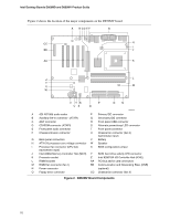 10
10 11
11

