Intel D865GBF Product Guide
Intel D865GBF - Desktop Board Motherboard Manual
 |
View all Intel D865GBF manuals
Add to My Manuals
Save this manual to your list of manuals |
Intel D865GBF manual content summary:
- Intel D865GBF | Product Guide - Page 1
Intel® Desktop Board D865GBF/D865GLC Product Guide Order Number: C24485-002 - Intel D865GBF | Product Guide - Page 2
Intel® Desktop Board D865GBF/D865GLC Product Guide. Second release of the Intel® Desktop Board D865GBF/D865GLC Product Guide the instructions, and on, the user is encouraged to Intel may make changes to specifications and product descriptions at any time, without notice. Desktop Board D865GBF/D865GLC - Intel D865GBF | Product Guide - Page 3
the desktop board and other hardware components. • 3 Updating the BIOS: instructions on how to update the BIOS. • 4 Using the BIOS Setup Program: contents of the BIOS Setup menus and submenus • 5 Technical Reference: information about connectors and desktop board resources. • A Error Messages and - Intel D865GBF | Product Guide - Page 4
Intel Desktop Boards D865GBF/D865GLC Product Guide Terminology The table below gives descriptions to some common terms used in the product guide. Term GB GHz KB MB Mbit MHz Description Gigabyte (1,073,741,824 bytes) Gigahertz (one billion hertz) Kilobyte (1024 bytes) Megabyte (1,048,576 bytes) - Intel D865GBF | Product Guide - Page 5
...16 Main Memory ...17 Intel® 865G Chipset...18 Graphics Subsystem ...18 Audio Subsystem ...18 Flexible 6-Channel Audio with Jack Sensing 18 Input/Output (I/O) Controller 19 LAN Subsystem (Optional 19 LAN Subsystem Software 19 RJ-45 LAN Connector LEDs 20 Hi-Speed USB 2.0 Support 20 Enhanced - Intel D865GBF | Product Guide - Page 6
the Front Panel Header 43 Connecting Hardware Control and Power Cables 44 Connecting the Chassis Intrusion Cable 45 Connecting Fans ...45 Connecting Power Cables 45 Setting the BIOS Configuration Jumper Block 46 Clearing Passwords ...47 Replacing the Battery ...48 3 Updating the BIOS Updating - Intel D865GBF | Product Guide - Page 7
Reference Board Connectors ...85 Back Panel Connectors 86 Audio Connectors ...87 Add-In Card and Peripheral Interface Connectors 88 Desktop Board Resources 89 Memory Map ...89 DMA Channels ...89 Interrupts ...90 A Error Messages and Indicators BIOS Beep Codes ...91 BIOS Error Messages...92 - Intel D865GBF | Product Guide - Page 8
15 5. Supported Processors 16 6. RJ-45 10/100 Ethernet LAN Connector LEDs 20 7. RJ-45 10/100/1000 Gigabit Ethernet LAN Connector LEDs 20 8. Front Panel Audio Header Signal Names (J9A2 41 9. USB 2.0 Headers (J9F1 and J9H1 43 10. Front Panel Header (J9J1 43 11. Jumper Settings for the BIOS Setup - Intel D865GBF | Product Guide - Page 9
Contents 41. Beep Codes ...91 42. BIOS Error Messages 92 43. Safety Regulations...95 44. EMC Regulations ...95 ix - Intel D865GBF | Product Guide - Page 10
Intel Desktop Boards D865GBF/D865GLC Product Guide x - Intel D865GBF | Product Guide - Page 11
. For more information about the latest list of tested memory, refer to the Intel World Wide Web site at: http://support.intel.com/support/motherboards/desktop/ Intel® 865G chipset consisting of: • Intel® 82865G Graphics and Memory Controller Hub (GMCH) with Accelerated Hub Architecture (AHA) bus - Intel D865GBF | Product Guide - Page 12
system temperature • Voltage sensing to detect out of range values Related Links: For more information about Intel Desktop Board D865GBF/D865GLC, including the Technical Product Specification (TPS), BIOS updates, and device drivers, go to: http://support.intel.com/support/motherboards/desktop/ 12 - Intel D865GBF | Product Guide - Page 13
RJ-45 connector Gigabit LAN Intel® 82540EI 10/100/1000 Mbit/sec Gigabit Ethernet controller and RJ-45 connector Supported Operating Systems The desktop board supports the following operating systems: • Microsoft Windows* 98 SE • Microsoft Windows Me • Microsoft Windows 2000 • Microsoft Windows XP - Intel D865GBF | Product Guide - Page 14
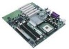
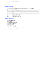
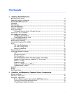
Intel Desktop Boards D865GBF/D865GLC Product Guide Desktop Board Components Figure 1 shows the approximate location of the major components on TRP O U SQ NM L Figure 1. Desktop Board D865GBF Components NOTE Desktop board D865GLC has three PCI bus add-in card connectors. F G H I J K OM15224 14 - Intel D865GBF | Product Guide - Page 15
socket Main power connector Diskette drive connector Primary IDE connector Secondary IDE connector Front chassis fan connector (fan speed control) Chassis intrusion header Serial ATA connectors Speaker BIOS configuration jumper Alternate power/sleep LED header Front panel header USB 2.0 header Intel - Intel D865GBF | Product Guide - Page 16
Links: Go to the following link or sections in this manual for more information about: • the latest information on supported Intel processors for Desktop Board D865GBF/D865GLC http://support.intel.com/support/motherboards/desktop/ • instructions on installing or upgrading the processor, page 32 in - Intel D865GBF | Product Guide - Page 17
Links: Go to the following links or section in this manual for more information about: • the latest list of tested memory, http://support.intel.com/support/motherboards/desktop/ • SDRAM specifications, http://www.intel.com/technology/memory/pcsdram/spec/ • installing memory, page 34 in Chapter 2 17 - Intel D865GBF | Product Guide - Page 18
that supports a single dynamic, condenser, or electret microphone The subsystem has the following connectors: • ATAPI-style CD-ROM connector • Front panel audio connector, including pins for: Line out Mic in • Back panel audio connectors that are configurable through the audio devices drivers - Intel D865GBF | Product Guide - Page 19
Board Features Related Links: Go to the following link or sections in this manual for more information about: • audio drivers and utilities, http://support.intel.com/support/motherboards/desktop/ • installing the front panel audio solution, page 41 in Chapter 2 • setting up the Flexible 6-Channel - Intel D865GBF | Product Guide - Page 20
Intel Desktop Boards D865GBF/D865GLC Product Guide RJ-45 LAN Connector LEDs Two LEDs are built into the RJ-45 LAN connector. Table 6 describes the LED states when the board is powered up and the 10/100 Ethernet LAN subsystem is operating. Table 6. RJ-45 10/100 Ethernet LAN Connector LEDs LED - Intel D865GBF | Product Guide - Page 21
card, see page 37 in Chapter 2. BIOS The BIOS provides the Power-On Self-Test (POST), the BIOS Setup program, the PCI and IDE auto-configuration utilities, and the video BIOS. The BIOS is stored in the Firmware Hub. The BIOS can be updated by following the instructions in Chapter 3 on page 53. PCI - Intel D865GBF | Product Guide - Page 22
Intel Desktop Boards D865GBF/D865GLC Product Guide Security Passwords The BIOS includes security features that restrict whether the BIOS Setup program can be accessed and who can boot the computer. A supervisor password and a user password can be set for the Setup and for booting the computer, with - Intel D865GBF | Product Guide - Page 23
front and rear chassis fan connectors. The processor fan connector is not controlled. The fan speed control feature can be disabled in the BIOS -to-RAM) sleep memory modules and PCI bus connectors, even when the computer appears to be off. If the system has a dual-colored power LED on the front panel - Intel D865GBF | Product Guide - Page 24
Intel Desktop Boards D865GBF/D865GLC Product Guide CR7J1 Figure 2. Location of Standby Power Indicator OM15225 CAUTION Power supplies used with this desktop board must be able to provide enough standby current to support the standard Instantly Available (ACPI S3 sleep state) configuration. If the - Intel D865GBF | Product Guide - Page 25
activity wakes the computer from an ACPI S1 or S3 state. PME# Wakeup Support When the PME# signal on the PCI bus is asserted, the computer wakes keeps the values in CMOS RAM and the clock current when the computer is turned off. See page 48 in Chapter 2 for instructions on how to replace the - Intel D865GBF | Product Guide - Page 26
Intel Desktop Boards D865GBF/D865GLC Product Guide 26 - Intel D865GBF | Product Guide - Page 27
memory • Install and remove an AGP card • Connect the IDE and Serial ATA cables • Connect internal headers • Connecting 6-Channel Flex Audio with Jack Sensing • Connect hardware control and power cables • Set the BIOS though the front panel power button is - Intel D865GBF | Product Guide - Page 28
Desktop Boards D865GBF/D865GLC Product Guide Installation Precautions When you install and test the Intel desktop board, observe all warnings and cautions in the installation instructions. To avoid injury, be careful of: • Sharp pins on connectors • Sharp pins on printed circuit assemblies • Rough - Intel D865GBF | Product Guide - Page 29
Canada statement at the front of this product guide demonstrates compliance with Canadian insufficient space on this desktop board to provide instructions for replacing and disposing of the Lithium ion Use Only for Intended Applications All Intel desktop boards are evaluated as Information - Intel D865GBF | Product Guide - Page 30
Intel Desktop Boards D865GBF/D865GLC Product Guide Installing the I/O Shield The desktop board comes with an I/O shield. When installed in the chassis, the shield blocks radio frequency transmissions, protects internal components from - Intel D865GBF | Product Guide - Page 31
the computer can result in personal injury or equipment damage. NOTE Refer to Appendix B for regulatory requirements. Refer to your chassis manual for instructions on installing and removing the desktop board. Figure 4 shows the location of the 11 mounting holes for Desktop Board D865GBF. Desktop - Intel D865GBF | Product Guide - Page 32
D865GBF/D865GLC has an integrated processor fan heat sink retention mechanism (RM). For instructions on how to install the processor fan heat sink to the integrated processor fan heat sink RM, refer to the boxed processor manual or the Intel World Wide Web site at: http://support.intel.com/support - Intel D865GBF | Product Guide - Page 33
Heat Sink Cable to the Processor Fan Connector Removing the Processor For instruction on how to remove the processor fan heat sink and processor, refer to the processor installation manual or the Intel World Wide Web site at: http://support.intel.com/support/processors/pentium4/intnotes478.htm 33 - Intel D865GBF | Product Guide - Page 34
memory specifications, the boards require DIMMs that support the Serial Presence Detect (SPD) data structure. You can access the PC Serial Presence Detect Specification at: http://www.intel.com/technology/memory/pcsdram/spec/ Desktop Board D865GBF/D865GLC has four dual channel 184-pin DIMM sockets - Intel D865GBF | Product Guide - Page 35
A 256 MB, 128 Mb, DDR400 DIMM 0 DIMM 1 Channel B 256 MB, 128 Mb, DDR400 Figure 8. Dual Configuration Example with Two DIMMs DIMM 0 DIMM 1 If additional memory is to be used, then install another matched pair of DIMMs in DIMM 1 in both channels A and B (see Figure 9). Channel A 256 MB, 128 Mb - Intel D865GBF | Product Guide - Page 36
Intel Desktop Boards D865GBF/D865GLC Product Guide CAUTION Install memory in the DIMM sockets prior to installing an AGP video card to avoid interference with the memory retention mechanism. To install DIMMs, follow these steps: 1. Observe the precautions in "Before You Begin" on page 27. 2. Turn - Intel D865GBF | Product Guide - Page 37
board components and/or traces may be damaged. The AGP connector supports 0.8 V (4x and 1x) and 1.5 V (8x) AGP cards. The desktop board has an integrated AGP card retention mechanism (RM). Installing an AGP Card Follow these instructions to install an AGP card: 1. Observe the precautions in "Before - Intel D865GBF | Product Guide - Page 38
Intel Desktop Boards D865GBF/D865GLC Product Guide Connecting the IDE Cable The two IDE cables support the Ultra DMA- • Attach the cable end with the single connector to the Intel desktop board (A). • Attach the cable end with the two closely spaced connectors to the drives (B). OM15238 A B Figure - Intel D865GBF | Product Guide - Page 39
Board Components Connecting the Serial ATA Cable The SATA cable (4-conductor) supports the Serial ATA protocol and connects a single drive to the desktop board. Either end of the cable can be connected to the SATA drive or the connector on the board (see Figure 12). For correct cable function - Intel D865GBF | Product Guide - Page 40
D865GBF/D865GLC Product Guide Connecting Internal Headers Figure 13 shows the location of internal headers. 1 2 3 4 A5 6 7 9 10 J9A2 1 3 C5 7 1 2 B3 5 4 6 7 8 10 2 4 J9F1 6 8 10 J9H1 1 2 3 4 5 6 D7 8 9 J9J1 E 12 Item A B C D E Description Front panel audio USB - Intel D865GBF | Product Guide - Page 41
. 3. Remove the cover. 4. Locate the front panel audio header. Remove the two jumpers from the header to disable the back panel audio connectors. 5. Install a correctly keyed and shielded front panel audio cable. 6. Connect the audio cable to the front panel audio solution. 7. Replace the cover. To - Intel D865GBF | Product Guide - Page 42
Intel Desktop Boards D865GBF/D865GLC Product Guide Setting up the Flexible 6-Channel Audio with Jack Sensing After installing the SoundMAX 4 XL audio driver from the Intel Express Installer CD-ROM, the multi-channel audio feature can now be enabled. See Figure 14 for back panel audio connectors. A - Intel D865GBF | Product Guide - Page 43
"Before You Begin" on page 27. Figure 13-C on page 40 shows the location of the front panel header. Table 10 shows the pin assignments for the front panel header. Table 10. Front Panel Header (J9J1) Pin Signal In/Out Description Pin Signal In/Out Description Hard Drive Activity LED Power LED - Intel D865GBF | Product Guide - Page 44
Intel Desktop Boards D865GBF/D865GLC Product Guide Connecting Hardware Control and Power Cables Figure 15 shows the location of the chassis intrusion and fan headers, and power connectors. Chassis rear fan 1 J6B1 12 V processor core voltage connector 1 2 Processor fan 1 J6B1 Chassis intrusion - Intel D865GBF | Product Guide - Page 45
on the board. Connect chassis fan cables to the board fan headers. See Figure 15 for fan header locations. Connecting Power Cables CAUTION Failure to use an ATX12V power supply, or not connecting the 12 V processor core voltage power supply connector to the desktop board may result in damage to the - Intel D865GBF | Product Guide - Page 46
Intel Desktop Boards D865GBF/D865GLC Product Guide Setting the BIOS Configuration Jumper Block CAUTION Always turn the BIOS displays the Maintenance Menu. Use this menu to clear passwords. 1 3 Recovery (None) The BIOS recovers data from a recovery diskette in the event of a failed BIOS update. 46 - Intel D865GBF | Product Guide - Page 47
Installing and Replacing Desktop Board Components Clearing Passwords This procedure assumes that the board is installed in the computer and the configuration jumper block is set to normal mode. 1. Observe the precautions in "Before You Begin" on page 27. 2. Turn off all peripheral devices connected - Intel D865GBF | Product Guide - Page 48
Intel Desktop Boards D865GBF/D865GLC Product Guide Replacing the Battery A coin-cell battery (CR2032) powers the real-time clock and CMOS memory. When the computer is not plugged into a wall socket below a certain level, the BIOS Setup program settings stored in CMOS RAM (for example, the date and - Intel D865GBF | Product Guide - Page 49
Installing and Replacing Desktop Board Components $99(57,0(172 Esiste il pericolo di un esplosione se la pila non viene sostituita in modo corretto. Utilizzare solo pile uguali o di tipo equivalente a quelle consigliate dal produttore. Per disfarsi delle pile usate, seguire le istruzioni del - Intel D865GBF | Product Guide - Page 50
Intel Desktop Boards D865GBF/D865GLC Product Guide $:$6 Risiko letupan wujud jika bateri digantikan dengan jenis yang tidak betul. Bateri sepatutnya dikitar semula jika boleh. Pelupusan bateri terpakai mestilah mematuhi peraturan alam sekitar - Intel D865GBF | Product Guide - Page 51
17). 5. With a medium flat-bladed screwdriver, gently pry the battery free from its connector. Note the orientation of the "+" and "-" on the battery. 6. Install the new battery in the connector, orienting the "+" and "-" correctly. 7. Replace the computer cover. Figure 17. Removing the Battery - Intel D865GBF | Product Guide - Page 52
Intel Desktop Boards D865GBF/D865GLC Product Guide 52 - Intel D865GBF | Product Guide - Page 53
Memory Update Utility and the ease-of use of Windows-based installation wizards. To update the BIOS with the Intel Express BIOS Update utility: 1. Go to the Intel World Wide Web site: http://support.intel.com/support/motherboards/desktop/ 2. Navigate to the Desktop Board D865GBF or D865GLC page - Intel D865GBF | Product Guide - Page 54
or D865GLC page on the Intel World Wide Web site: http://support.intel.com/support/motherboards/desktop NOTE Review the instructions distributed with the update utility before attempting a BIOS update. The Intel Flash Memory Update Utility allows you to: • Update the BIOS in flash memory • Update - Intel D865GBF | Product Guide - Page 55
steps explain how to recover the BIOS if an update fails. The following procedure uses recovery mode for the Setup program. See page 46 for more information on Setup modes. NOTE Because of the small amount of code available in the boot block area, there is no video support. You will not see anything - Intel D865GBF | Product Guide - Page 56
Intel Desktop Boards D865GBF/D865GLC Product Guide 56 - Intel D865GBF | Product Guide - Page 57
section may not show the latest settings. For the latest BIOS settings, refer to the Intel® Desktop Board D865GBF/D865GLC Technical Product Specification or the Intel World Wide Web site: http://support.intel.com/support/motherboards/desktop NOTE For reference purposes, you should write down the - Intel D865GBF | Product Guide - Page 58
Intel Desktop Boards D865GBF/D865GLC Product Guide Table 13 shows the function keys available for menu screens. Table 13. BIOS Setup Program Function Keys BIOS Update Rev user and supervisor passwords. • Cancel Clear BIS Credentials • Ok Clears the Wired for Management Boot Integrity Service - Intel D865GBF | Product Guide - Page 59
Power Boot Exit BIOS Version xxxxx10A.86A.xxxx.xxx Processor Type Hyper-Threading Technology Processor Speed System Bus Speed System Memory Speed Intel(R) Pentium(R) 4 [Enabled] X.XX GHz XXX MHz XXX MHz Cache RAM XXX KB Total Memory Memory Mode Memory Channel A Slot 0 Memory Channel A Slot - Intel D865GBF | Product Guide - Page 60
Intel Desktop Boards D865GBF/D865GLC Product Guide Advanced Menu Main Advanced Security Power Boot Exit Setup Warning: Setting items Configuration No options No options Event Log Configuration No options Video Configuration No options USB Configuration No options Chipset Configuration No - Intel D865GBF | Product Guide - Page 61
Using the BIOS Setup Program PCI Configuration Submenu Main Advanced Security Power Boot Exit PCI Configuration PCI Slot 1 IRQ Priority PCI Slot 2 IRQ Priority PCI Slot 3 IRQ Priority - Intel D865GBF | Product Guide - Page 62
Intel Desktop Boards D865GBF/D865GLC Product Guide Boot Configuration Submenu Main Advanced Security Power Boot Exit Boot • Yes • Off • On (default) Description Specifies if manual configuration is desired. No lets the BIOS configure all devices in the system. This setting is appropriate - Intel D865GBF | Product Guide - Page 63
Using the BIOS Setup Program Peripheral Configuration Submenu Main Advanced Security Power Boot Exit Peripheral Configuration Serial Port A Parallel Port Mode LAN Device Audio [Auto] [Auto] [Bi-directional] [Enabled] [Enabled] m o n p Enter F1 P9 F10 ESC Select Screen Select Item Select ` Sub - Intel D865GBF | Product Guide - Page 64
Intel Desktop Boards D865GBF/D865GLC Product Guide Table 19. Peripheral Configuration Submenu (continued) Feature Port is set to Enabled) LAN Device (This feature is present only when there is onboard LAN) Audio Options • Output only • Bi-directional (default) • EPP • ECP • 378 (default) • 278 - Intel D865GBF | Product Guide - Page 65
Using the BIOS Setup Program ATA/IDE Configuration Submenu Main Advanced Security Power Boot Exit IDE Configuration PCI device to initiate a transaction as a master. Specifies the hard disk drive pre-delay. Causes the BIOS to insert a delay before attempting to detect IDE drives in the system. 65 - Intel D865GBF | Product Guide - Page 66
Intel Desktop Boards D865GBF/D865GLC Product Guide PATA and SATA Submenus Main Advanced Security Power Boot Exit ` [SATA Port-0 : Xxxxxxxx ] Type Maximum Capacity [Auto] [Auto] Configuration Options Selected by BIOS LBA Mode : Block Mode: PIO Mode : Ultra DMA : Cable Detected : [Supported] - Intel D865GBF | Product Guide - Page 67
Using the BIOS Setup Program Table 21. SATA and PATA Submenus (continued) Feature DMA Mode S.M.A.R.T. Cable Detected (Note) Options • Auto (default) • SWDMA 0 • SWDMA 1 • SWDMA 2 • MWDMA 0 • MWDMA 1 • MWDMA 2 • UDMA 0 • - Intel D865GBF | Product Guide - Page 68
Intel Desktop Boards D865GBF/D865GLC Product Guide Diskette Configuration Submenu Main Advanced Security Diskette Configuration Power Boot Diskette Controller [Enabled] Floppy A [1.44/1.25MB 3½"] Diskette Write Protect [Disabled] Exit m o n p Enter F1 P9 F10 - Intel D865GBF | Product Guide - Page 69
Using the BIOS Setup Program Event Log Configuration Submenu Main Advanced Security Event Log Configuration Power Boot Event Log [Space Available] View Event Log Clear Event Log Event - Intel D865GBF | Product Guide - Page 70
Intel Desktop Boards D865GBF/D865GLC Product Guide Video Configuration Submenu Main Advanced Security Video Configuration Power Boot Exit AGP Aperture Size Primary Video of system memory available for direct access by the graphics device. Allows selecting an AGP or PCI video controller as - Intel D865GBF | Product Guide - Page 71
BIOS Setup Program USB Configuration Submenu Main Advanced Security Power USB Configuration High-Speed USB Legacy USB Support Support Options • Disabled • Enabled (default) • Disabled • Enabled (default) Description Disable this option when a USB 2.0 driver is not available. Enables support - Intel D865GBF | Product Guide - Page 72
Intel Desktop Boards D865GBF/D865GLC Product Guide Chipset Configuration Submenu Main Advanced [Auto] Do you wish to continue? Burn-In Mode [Continue] [Default] Extended Configuration Chipset Memory Timing Control Graphics Core Frequency SDRAM Frequency [Default] [Auto] [Auto] m o n p - Intel D865GBF | Product Guide - Page 73
frequency value. Auto allows timings to be programmed according to the memory detected. Manual - Aggressive selects the most aggressive user defined timings. Manual - User Defined allows manual override of detected SDRAM settings. Controls Command Per Clock/1n rule mode. When enabled, allows DRAM - Intel D865GBF | Product Guide - Page 74
Intel Desktop Boards D865GBF/D865GLC Product Guide Fan Control Submenu Main Advanced Security Fan Control Configuration Power Boot Exit Setup Warning: These options will not take effect until power has been completely removed from the system. After saving the BIOS settings and turning the - Intel D865GBF | Product Guide - Page 75
Using the BIOS Setup Program Hardware Monitoring Submenu Main Advanced System Zone 2 Temperature 44oC/111oF 37oC/98oF 35oC/95oF Processor Fan Speed Rear Fan Speed (J1B1) Rear Fan Speed (J5B1) Front Fan Speed 2394 RPM 0 RPM 0 RPM 0 RPM +1.5Vin Vccp +3.3Vin +5Vin 12Vin 1.480 V 1.447 V 3.258 - Intel D865GBF | Product Guide - Page 76
Intel Desktop Boards D865GBF/D865GLC Product Guide Security Menu Main Advanced Security Power Boot Exit Supervisor Password : User Password : Not Installed Not Installed Set Supervisor Password Set User Password Chassis Intrusion [Disabled] m o n p Enter F1 P9 F10 ESC Select Screen Select - Intel D865GBF | Product Guide - Page 77
Using the BIOS Setup Program Power Menu Main ` ACPI Advanced Security Power Boot Exit After Power Failure [Last State] The options below are not related to ACPI and - Intel D865GBF | Product Guide - Page 78
Boards D865GBF/D865GLC Product Guide ACPI Submenu Main Advanced Security Power Boot Exit Advanced Configuration and Power Interface ACPI Suspend State Wake on LAN from S5 [S1 State] [Stay Off] S1 is the safest mode but consumes more power. S3 consumes low power but drivers may not support this - Intel D865GBF | Product Guide - Page 79
menu shown in Table 32 is used to set the boot features and the boot sequence. Table 32. Boot Menu Feature Silent Boot Intel® Rapid BIOS Boot Scan User Flash Area PXE Boot to LAN USB Boot Boot Device Priority Hard Disk Drives Removable Devices ATAPI CD-ROM Drives Options Description • Disabled - Intel D865GBF | Product Guide - Page 80
Intel Desktop Boards D865GBF/D865GLC Product Guide Boot Device Priority Submenu Main Advanced Security Power Boot settings for the first through final boot devices are, respectively listed below. The BIOS supports up to sixteen total boot devices in any combination of the boot device types - Intel D865GBF | Product Guide - Page 81
Using the BIOS Setup Program Hard Disk Drives Submenu Main Advanced Security Power Boot Exit 1st Drive 2nd Drive 3rd Drive 4th Drive [xxxxxxxxxxxxx] [xxxxxxxxxxxxx is installed. This list will display up to 12 hard disk drives, the maximum number of hard disk drives supported by the BIOS. 81 - Intel D865GBF | Product Guide - Page 82
Intel Desktop Boards D865GBF/D865GLC Product Guide Removable Devices Submenu Main Advanced Security Power Boot Exit 1st Drive [1st FLOPPY DRIVE] Specifies the boot installed. This list will display up to four removable devices, the maximum number of removable devices supported by the BIOS. 82 - Intel D865GBF | Product Guide - Page 83
Using the BIOS Setup Program ATAPI CD-ROM Drives Main Advanced Security Power Boot Exit 1st Drive 2nd Drive [xxxxxxx] [xxxxxxx] Specifies the boot type is installed. This list will display up to four ATAPI CD-ROM drives, the maximum number of ATAPI CD-ROM drives supported by the BIOS. 83 - Intel D865GBF | Product Guide - Page 84
Intel Desktop Boards D865GBF/D865GLC Product Guide Exit Menu Main Advanced Security Power Boot Exit Exit Saving Changes Exit Normally, the BIOS reads the Setup values from flash memory. If this memory is corrupted, the BIOS reads the custom defaults. If no custom defaults are set, the BIOS reads the - Intel D865GBF | Product Guide - Page 85
This chapter shows the location of the: • Back panel connectors • Audio connectors • Add-in board and peripheral interface connectors CAUTION Many of the midboard and front panel connectors provide operating voltage (+5 V dc and +12 V dc, for example) to devices inside the computer chassis - Intel D865GBF | Product Guide - Page 86
Intel Desktop Boards D865GBF/D865GLC Product Guide Back Panel Connectors NOTE The line out connector, located on the back panel, is designed to power either headphones or amplified speakers only. Poor audio quality may occur if passive (non-amplified) speakers are connected to this output. Figure 18 - Intel D865GBF | Product Guide - Page 87
Connectors Figure 13 shows the approximate location of the audio connectors. A 1 2 3 4 J9C1 B 1 2 3 4 5 6 7 9 10 J9A2 C 1 2 3 4 J8B1 Technical Reference Item Description A CD-ROM (ATAPI-style) B Front panel audio C Auxiliary line in (ATAPI-style) Figure 19. Audio Connectors - Intel D865GBF | Product Guide - Page 88
Intel Desktop Boards D865GBF/D865GLC Product Guide Add-In Card and Peripheral Interface Connectors Figure 20 shows the PCI bus add-in card and peripheral interface connectors for Desktop Board D865GBF. Desktop Board D865GLC has three PCI bus add-in card connectors. AB C DE FG OM15238 Item A B C D - Intel D865GBF | Product Guide - Page 89
KB 1 KB 127 KB 512 KB Description Extended Memory Runtime BIOS Reserved Available high DOS memory (open to the PCI bus) Video memory and BIOS Extended BIOS data (movable by memory manager software) Extended conventional memory Conventional memory DMA Channels Table 39. DMA Channels DMA Channel - Intel D865GBF | Product Guide - Page 90
Intel Desktop Boards D865GBF/D865GLC Product Guide Interrupts Table 40. Interrupts IRQ System Resource NMI I/O channel present, else user available) 13 Reserved, math coprocessor 14 Primary IDE (if present, else user available) 15 Secondary IDE (if present, else user available) * - Intel D865GBF | Product Guide - Page 91
D865GBF/D865GLC reports POST errors in two ways: • By sounding a beep code • By displaying an error message on the monitor BIOS Beep Codes The BIOS beep codes are listed in Table 41. The BIOS also issues a beep code (one long tone followed by two short tones) during POST if the video configuration - Intel D865GBF | Product Guide - Page 92
Intel Desktop Boards D865GBZ/D865GLC Product Guide BIOS Error Messages When a recoverable error occurs during the POST, the BIOS displays an error message describing the problem. Table 42. BIOS Checksum Bad The CMOS checksum is incorrect. CMOS memory may have been corrupted. Run Setup to reset - Intel D865GBF | Product Guide - Page 93
since the last boot. If no memory was removed, then memory may be bad. Memory size has increased since the last boot. If no memory was added, there may be a problem with the system. Memory size has changed since the last boot. If no memory was added or removed, then memory may be bad. System did not - Intel D865GBF | Product Guide - Page 94
Intel Desktop Boards D865GBZ/D865GLC Product Guide 94 - Intel D865GBF | Product Guide - Page 95
Business Equipment. (International) Summary of Nordic deviations to EN 60950. (Norway, Sweden, Denmark, and Finland) EMC Regulations Desktop Board D865GBF/D865GLC complies with the EMC regulations stated in Table 44 when correctly installed in a compatible host system. Table 44. EMC Regulations - Intel D865GBF | Product Guide - Page 96
Intel Desktop Boards D865GBZ/D865GLC Product Guide Product Certification Markings Desktop Board D865GBF/D865GLC has the following product certification markings: • UL joint US/Canada Recognized Component mark: consists of small c followed by a stylized backward UR and followed by a small - Intel D865GBF | Product Guide - Page 97
Regulatory Compliance • Korean Class B statement translated as follows: this is household equipment that is certified to comply with EMC requirements. You may use this equipment in residential environments and other non-residential environments. 97 - Intel D865GBF | Product Guide - Page 98
Intel Desktop Boards D865GBZ/D865GLC Product Guide 98
-
 1
1 -
 2
2 -
 3
3 -
 4
4 -
 5
5 -
 6
6 -
 7
7 -
8
-
9
-
10
-
11
-
12
-
13
-
14
-
15
-
16
-
17
-
18
-
19
-
20
-
21
-
22
-
23
-
24
-
25
-
26
-
27
-
28
-
29
-
30
-
31
-
32
-
33
-
34
-
35
-
36
-
37
-
38
-
39
-
40
-
41
-
42
-
43
-
44
-
45
-
46
-
47
-
48
-
49
-
50
-
51
-
52
-
53
-
54
-
55
-
56
-
57
-
58
-
59
-
60
-
61
-
62
-
63
-
64
-
65
-
66
-
67
-
68
-
69
-
70
-
71
-
72
-
73
-
74
-
75
-
76
-
77
-
78
-
79
-
80
-
81
-
82
-
83
-
84
-
85
-
86
-
87
-
88
-
89
-
90
-
91
-
92
-
93
-
94
-
95
-
96
-
97
-
98
 |
 |
Intel
®
Desktop Board
D865GBF/D865GLC
Product Guide
Order Number:
C24485-002