Intel D865GVHZ Product Guide
Intel D865GVHZ - Desktop Board - Mainboard Manual
 |
UPC - 675900599772
View all Intel D865GVHZ manuals
Add to My Manuals
Save this manual to your list of manuals |
Intel D865GVHZ manual content summary:
- Intel D865GVHZ | Product Guide - Page 1
Intel® Desktop Board D865GVHZ Product Guide Order Number: C70847-001 - Intel D865GVHZ | Product Guide - Page 2
Intel® Desktop Board D865GVHZ Product Guide. Date March 2004 If an FCC declaration of conformity marking is present on the board and used in accordance with the instructions, may cause harmful interference to is provided in connection with Intel® products. No license, express or implied, by estoppel - Intel D865GVHZ | Product Guide - Page 3
and Replacing Desktop Board Components: instruction on how to install the desktop board and other hardware components. 3 Updating the BIOS: instructions on how to update the BIOS. 4 Using the BIOS Setup Program: contents of the BIOS Setup menus and submenus. 5 Desktop Board Resources: Memory map - Intel D865GVHZ | Product Guide - Page 4
Intel Desktop Board D865GVHZ Product Guide Notations Term GB KB MB Mbit MHz * Description Gigabyte (1,073,741,824 bytes) Kilobyte (1024 bytes) Megabyte (1,048,576 bytes) Megabit (1,048,576 bits) Megahertz ( - Intel D865GVHZ | Product Guide - Page 5
1 Desktop Board Features Supported Operating Systems 10 Desktop Board Components 11 Processor ...13 Main Memory ...14 Intel® 865GV Chipset ...15 Graphics Subsystem ...15 Audio Subsystem ...15 LAN Subsystem ...15 LAN Subsystem Software 15 RJ-45 LAN Connector LEDs 15 Input/Output (I/O) Controller - Intel D865GVHZ | Product Guide - Page 6
Header 34 Installing a Front Panel Audio Solution 35 Connecting Hardware Control and Power Cables 36 Connecting the Chassis Intrusion Cable 37 Connecting Fans ...37 Connecting Power Supply Cables 37 Add-In Card and Peripheral Interface Connectors 38 Setting the BIOS Configuration Jumper Block - Intel D865GVHZ | Product Guide - Page 7
11. PCI Bus Add-in Card and Peripheral Interface Connectors 38 12. Location of the BIOS Configuration Jumper Block 39 13. Back Panel Connectors 41 14. Removing the Battery 45 Tables 1. Feature Summary ...9 2. Desktop Board Components 12 3. Supported Processors 13 4. RJ-45 10/100 Ethernet LAN - Intel D865GVHZ | Product Guide - Page 8
Intel Desktop Board D865GVHZ Product Guide 10. BIOS Setup Program Function Keys 52 11. Maintenance Menu ...52 12. Main Menu...53 13. Advanced Menu...54 14. PCI Configuration Submenu 55 15. Boot Configuration Submenu 56 16. Peripheral Configuration Submenu 57 17. ATA/IDE Configuration Submenu 59 - Intel D865GVHZ | Product Guide - Page 9
PCI bus add-in card connectors (SMBus routed to PCI bus 2) BIOS • Intel/AMI BIOS • 4 Mbit symmetrical flash memory • Support for SMBIOS Power Management • Support for Advanced Configuration and Power Interface (ACPI) • Suspend to RAM (STR) • Wake on USB, PCI, RS-232, PS/2, LAN, and front panel - Intel D865GVHZ | Product Guide - Page 10
about Intel Desktop Board D865GVHZ, including the Technical Product Specification (TPS), BIOS updates, and device drivers, go to: http://support.intel.com/support/motherboards/desktop/ Supported Operating Systems The desktop board supports the following operating systems: • Microsoft Windows* 98 - Intel D865GVHZ | Product Guide - Page 11
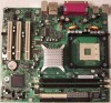
Desktop Board Features Desktop Board Components Figure 1 shows the approximate location of the major components on Desktop Board D865GVHZ. Line In USB 2.0 A B C USB 2.0 D X E W V U T S R Q P ON M L K J Figure 1. Desktop Board D865GVHZ Components F G H I OM17019 11 - Intel D865GVHZ | Product Guide - Page 12
Intel Desktop Board D865GVHZ Product Guide Table 2. Label A B C D E F G H I J K L M N O P Q R S T U V W X Desktop Board Components Description CD-ROM audio connector (ATAPI-style) Front panel audio header Rear chassis fan header 12 V processor core voltage connector Processor socket Processor fan - Intel D865GVHZ | Product Guide - Page 13
in this manual for more information about: • The latest supported Intel processors for Desktop Board D865GVHZ http://support.intel.com/support/motherboards/desktop/ • Installing or upgrading the processor, page 26 in Chapter 2 • The location of the ATX12V compliant power supply connectors, page 37 - Intel D865GVHZ | Product Guide - Page 14
controller for normal operation. The desktop board supports system memory as defined below: • Dual channel and up to four 184-pin Double Data Rate (DDR) SDRAM Dual Inline Memory Module (DIMMs) connectors with gold-plated contacts. • Supported memory configurations are: Memory Speed Processor Front - Intel D865GVHZ | Product Guide - Page 15
chipset (AC '97) • Realtek ALC202A audio codec Related Links Go to the following link or sections in this manual for more information about: • Audio drivers and utilities, http://support.intel.com/support/motherboards/desktop/ • Installing the front panel audio solution, page 34 in Chapter 2 LAN - Intel D865GVHZ | Product Guide - Page 16
Intel Desktop Board D865GVHZ Product Guide Table 4. RJ-45 10/100 Ethernet LAN Connector LEDs LED Color Green Yellow LED State Off On Off On (steady state) On (brighter and pulsing) Indicates 10 Mbit/sec data rate is selected. 100 Mbit/sec data rate is selected. LAN link is not established. LAN - Intel D865GVHZ | Product Guide - Page 17
• Laser Servo (LS-120) drives BIOS The BIOS provides the Power-On Self-Test (POST), the BIOS Setup program, the PCI and IDE auto-configuration utilities, and the video BIOS. The BIOS is stored in the Firmware Hub. The BIOS can be updated by following the instructions in Chapter 3 on page 47 - Intel D865GVHZ | Product Guide - Page 18
of the power connectors. Fan Connectors The desktop board has two chassis fan connectors (Intel Precision Cooling Technology) and one processor fan connector. See Figure 10 on page 36 for the location of the fan connectors. Fan Speed Control (Intel® Precision Cooling Technology) Intel Precision - Intel D865GVHZ | Product Guide - Page 19
Desktop Board Features The fan speed control feature can be disabled in the BIOS, resulting in the chassis fans always operating at full speed. This feature should be disabled if a self-controlled fan is attached to a chassis fan connector. Overall system noise reduction will vary based on system - Intel D865GVHZ | Product Guide - Page 20
Intel Desktop Board D865GVHZ Product Guide PME# Wakeup Support When the PME# signal on the PCI bus is asserted, the computer wakes from an ACPI S1, S3, or S5 state. Speaker A speaker is mounted on the desktop board. The speaker provides audible error code (beep code) information during the Power-On - Intel D865GVHZ | Product Guide - Page 21
• Install and remove the desktop board • Install and remove a processor and memory • Connect the IDE and/or Serial ATA cable • Connect internal headers • Connect hardware control and power cables • Locate the add-in card and peripheral interface connectors • Set the BIOS configuration jumper • Clear - Intel D865GVHZ | Product Guide - Page 22
test the Intel desktop board, observe all warnings and cautions in the installation instructions. To avoid injury, be careful of: • Sharp pins on connectors • Sharp pins on printed circuit assemblies • Rough edges and sharp corners on the chassis • Hot components (like processors, voltage regulators - Intel D865GVHZ | Product Guide - Page 23
. The Industry Canada statement at the front of this product guide demonstrates compliance with Canadian EMC regulations. of each of the power supplies output circuits. Place Battery Marking There is insufficient space on this desktop board to provide instructions for replacing and disposing - Intel D865GVHZ | Product Guide - Page 24
Intel Desktop Board D865GVHZ Product Guide Use Only for Intended Applications All Intel desktop boards are evaluated as Information Technology Equipment (I.T.E.) for use in personal computers for installation in homes, offices, schools, computer rooms, and similar locations. The suitability of - Intel D865GVHZ | Product Guide - Page 25
damage. NOTE Refer to Appendix B for regulatory requirements. Refer to your chassis manual for instructions on installing and removing the desktop board. Figure 3 shows the location of the six mounting screw holes for Desktop Board D865GVHZ. Figure 3. Location of Mounting Screw Holes OM17021 25 - Intel D865GVHZ | Product Guide - Page 26
Installing the Processor Fan Heat Sink Desktop Board D865GVHZ has an integrated processor fan heat sink retention mechanism (RM). For instructions on how to install the processor fan heat sink to the integrated processor fan heat sink RM, refer to the boxed processor manual or the Intel World Wide - Intel D865GVHZ | Product Guide - Page 27
Desktop Board Components Connecting the Processor Fan Heat Sink Cable Connect the processor fan heat sink cable to the processor fan connector (see Figure 5). OM17022 Figure 5. Connecting the Processor Fan Heat Sink Cable to the Processor Fan Connector Removing the Processor For instruction - Intel D865GVHZ | Product Guide - Page 28
with all applicable Intel SDRAM memory specification addendums, the board requires DIMMs that support the Serial Presence Detect (SPD) data structure. You can access the PC Serial Presence Detect Specification at: http://www.intel.com/technology/memory/pcsdram/spec/ Desktop Board D865GVHZ has two - Intel D865GVHZ | Product Guide - Page 29
Desktop Board Components Installing DIMMs To install DIMMs, follow these steps: 1. Observe the precautions in "Before You Begin" on page 21. 2. Turn off all peripheral devices connected to the computer. Turn off the computer and disconnect the AC power power cord. Removing DIMMs To remove a memory - Intel D865GVHZ | Product Guide - Page 30
Intel Desktop Board D865GVHZ Product Guide Connecting the IDE Cable The two IDE cables support the Ultra DMA-33 and ATA-66/100 transfer protocols. Each of the cables can connect two drives to the desktop board. Figure 7 shows the correct installation of the cable. NOTE ATA-66/100 compatible cables - Intel D865GVHZ | Product Guide - Page 31
OM17024 Connecting the Serial ATA Cable The SATA cable (4-conductor) supports the Serial ATA protocol and connects a single drive to the desktop board. Either end of the cable can be connected to the SATA drive or the connector on the board (see Figure 8). For correct cable function: 1. Observe - Intel D865GVHZ | Product Guide - Page 32
Intel Desktop Board D865GVHZ Product Guide OM15238 A B Figure 8. Connecting the Serial ATA Cable OM17025 32 - Intel D865GVHZ | Product Guide - Page 33
Desktop Board Components Connecting Internal Headers Figure 9 shows the location of internal headers. 1 2 3 4 A5 6 7 9 10 F 432 1 1 2 3 4 E5 6 7 8 10 1 2 3 4 D5 6 7 8 10 B 13 24 68 C 1 3 57 9 Item A B C D E F Description Front panel audio Alternate power/sleep - Intel D865GVHZ | Product Guide - Page 34
Intel Desktop Board D865GVHZ Product Guide Connecting the Front Panel Header Before connecting the front panel header, observe the precautions in "Before You Begin" on page 21. Figure 9-C on page 33 shows the location of the front panel header. Table 5 shows the pin assignments for the front panel - Intel D865GVHZ | Product Guide - Page 35
the AC power cord. 3. Remove the cover. 4. Locate the front panel audio header. Remove the two jumpers from the header to disable the back panel audio connectors. 5. Install a correctly keyed and shielded front panel audio cable. 6. Connect the audio cable to the front panel audio solution - Intel D865GVHZ | Product Guide - Page 36
Intel Desktop Board D865GVHZ Product Guide Connecting Hardware Control and Power Cables Figure 10 shows the location of the chassis intrusion and fan headers, and power connectors. Chassis rear fan 1 12 V Processor core voltage connector 1 2 Processor fan 1 Chassis intrusion connector 1 - Intel D865GVHZ | Product Guide - Page 37
processor fan header on the board. Connect chassis fan cables to the board fan headers. See Figure 10 for fan header locations. Connecting Power Supply Cables CAUTION Failure to use an ATX12V power supply, or not connecting the 12 V processor core voltage power supply connector to the desktop board - Intel D865GVHZ | Product Guide - Page 38
Intel Desktop Board D865GVHZ Product Guide Add-In Card and Peripheral Interface Connectors Figure 11 shows the PCI bus add-in card and peripheral interface connectors for Desktop Board D865GVHZ. ABC F E D Item A B C D E F Description PCI bus add-in card connector 3 PCI bus add-in card connector - Intel D865GVHZ | Product Guide - Page 39
Configuration Jumper Block CAUTION Always turn off the power and unplug the power cord from the computer before changing the jumper. Moving the jumper with the power on may result in unreliable computer operation. The location of the desktop board's BIOS configuration jumper is shown in Figure 12 - Intel D865GVHZ | Product Guide - Page 40
Intel Desktop Board D865GVHZ Product Guide Clearing BIOS Passwords This procedure assumes that the board is installed in the computer and the BIOS the Setup program. Setup displays the Maintenance menu. 8. Use the arrow keys to select Clear Passwords. Press and Setup displays a pop-up screen - Intel D865GVHZ | Product Guide - Page 41
Installing and Replacing Desktop Board Components Back Panel Connectors NOTE The line out connector, located on the back panel, is designed to power either headphones or amplified speakers only. Poor audio quality may occur if passive (non-amplified) speakers are connected to this output. Figure 13 - Intel D865GVHZ | Product Guide - Page 42
Intel Desktop Board D865GVHZ Product Guide Replacing the Battery A coin-cell battery (CR2032) powers the real-time clock and CMOS memory. When the computer is not plugged into a wall socket, the battery has an estimated life of three years. When the computer is plugged in, the - Intel D865GVHZ | Product Guide - Page 43
Installing and Replacing Desktop Board Components AVVERTIMENTO Esiste il pericolo di un esplosione se la pila non viene sostituita in modo corretto. Utilizzare solo pile uguali o di tipo equivalente a quelle - Intel D865GVHZ | Product Guide - Page 44
Intel Desktop Board D865GVHZ Product Guide AWAS Risiko letupan wujud jika bateri digantikan dengan jenis yang tidak betul. Bateri sepatutnya dikitar semula jika boleh. Pelupusan bateri terpakai mestilah mematuhi peraturan alam - Intel D865GVHZ | Product Guide - Page 45
computer. Disconnect the computer's power cord from the AC power source (wall outlet or power adapter). 3. Remove the computer cover. 4. Locate the battery on the board (see Figure 14). 5. With a medium flat-bladed screwdriver, gently pry the battery free from its connector. Note the orientation of - Intel D865GVHZ | Product Guide - Page 46
Intel Desktop Board D865GVHZ Product Guide 46 - Intel D865GVHZ | Product Guide - Page 47
Intel® Flash Memory Update Utility and the ease-of use of Windows-based installation wizards. To update the BIOS with the Intel Express BIOS Update utility: 1. Go to the Intel World Wide Web site: http://support.intel.com/support/motherboards/desktop/ 2. Navigate to the Desktop Board D865GVHZ page - Intel D865GVHZ | Product Guide - Page 48
to the Desktop Board D865GVHZ page on the Intel World Wide Web site: http://support.intel.com/support/motherboards/desktop NOTE Review the instructions distributed with the update utility before attempting a BIOS update. The Intel Flash Memory Update Utility allows you to: • Update the BIOS in flash - Intel D865GVHZ | Product Guide - Page 49
steps explain how to recover the BIOS if an update fails. The following procedure uses recovery mode for the Setup program. See page 39 for more information on Setup modes. NOTE Because of the small amount of code available in the boot block area, there is no video support. You will not see anything - Intel D865GVHZ | Product Guide - Page 50
Intel Desktop Board D865GVHZ Product Guide 50 - Intel D865GVHZ | Product Guide - Page 51
section may not show the latest settings. For the latest BIOS settings, refer to the Intel® Desktop Board D865GVHZ Technical Product Specification or the Intel World Wide Web site: http://support.intel.com/support/motherboards/desktop NOTE For reference purposes, you should write down the current - Intel D865GVHZ | Product Guide - Page 52
Intel Desktop Board D865GVHZ Product Guide Table 10 shows the function keys available for menu screens. Table 10. BIOS Setup Program Function Keys BIOS Setup Program Function Key < > or < > < > or < > Description Selects a different menu screen Moves cursor up or - Intel D865GVHZ | Product Guide - Page 53
the BIOS. Displays processor type. Enables or disables Hyper-Threading Technology. Displays processor speed. Displays the system bus speed. Displays the current system memory speed. Displays the size of second-level cache and whether it is ECC-capable. Displays the total amount of RAM. Displays the - Intel D865GVHZ | Product Guide - Page 54
Intel Desktop Board D865GVHZ Product Guide Advanced Menu Main Advanced Security Power Boot Exit Setup Warning: Setting items on this screen to incorrect values may cause your system to malfunction! PCI Configuration Boot Configuration Peripheral Configuration IDE Configuration Diskette - Intel D865GVHZ | Product Guide - Page 55
Using the BIOS Setup Program PCI Configuration Submenu Main Advanced Security Power Boot Exit PCI Configuration PCI Slot 1 IRQ Priority PCI Slot 2 IRQ Priority PCI Slot 3 IRQ Priority [Auto] Enter F1 P9 F10 ESC Select Screen Select Item Select Sub-Menu General Help Setup Defaults Save and Exit - Intel D865GVHZ | Product Guide - Page 56
Intel Desktop Board D865GVHZ Product Guide Boot Configuration Submenu Main Advanced Security Power Boot Exit Boot Configuration Plug & Play O/S Numlock ASF Support [No] [On] [Enabled] Enter F1 P9 F10 ESC Select Screen Select Item Select Sub-Menu General Help Setup Defaults Save and Exit Exit - Intel D865GVHZ | Product Guide - Page 57
Using the BIOS Setup Program Peripheral Configuration Submenu Main Advanced Security Power Boot Exit Peripheral Configuration Serial Port A Parallel Port Mode [Auto] [Auto] [Bi-directional] Audio Onboard LAN ASF Support [Enabled] [Enabled] [Enabled] Enter F1 P9 F10 ESC Select Screen Select - Intel D865GVHZ | Product Guide - Page 58
Intel Desktop Board D865GVHZ Product Guide Table 16. Peripheral Configuration Submenu (continued) Feature Mode Base I/O Address (This feature is present only when Parallel Port is set to Enabled) Interrupt (This feature is present only when Parallel Port is set to Enabled) Audio Onboard LAN (This - Intel D865GVHZ | Product Guide - Page 59
BIOS Setup Program ATA/IDE Configuration Submenu Main Advanced Security Power IDE Configuration Boot Exit ATA/IDE Configuration Legacy IDE Channels PCI BIOS to insert a delay before attempting to detect IDE drives in the system. NOTE: SATA hard drives are not supported on desktop board D865GVHZ. - Intel D865GVHZ | Product Guide - Page 60
from ATA/ATAPI device. User allows capabilities to be changed. Displays the capacity of the drive. Specifies LBA mode control. Check the hard disk drive's specifications for optimum setting. Specifies the PIO mode. NOTE: SATA hard drives are not supported on desktop board D865GVHZ. continued 60 - Intel D865GVHZ | Product Guide - Page 61
Using the BIOS Setup Program Table 18. SATA and PATA Submenus (continued) Feature DMA Mode S.M.A.R.T. Cable Detected (Note) Options • Auto (default) • SWDMA 0 mode for the drive. Self-monitoring analysis and reporting technology. Displays the type of cable connected to the IDE interface: 40- - Intel D865GVHZ | Product Guide - Page 62
Intel Desktop Board D865GVHZ Product Guide Diskette Configuration Submenu Main Advanced Security Diskette Configuration Power Boot Diskette Controller [Enabled] Floppy A [1.44/1.25MB 3½"] Diskette Write Protect [Disabled] Exit Enter F1 P9 F10 ESC Select Screen Select Item Select Sub- - Intel D865GVHZ | Product Guide - Page 63
Using the BIOS Setup Program Event Log Configuration Submenu Main Advanced Security Event Log Configuration Power Boot Event Log [ ) [Enter] Description Indicates if there is space available in the event log. Displays the contents of the DMI event log. Discards all events in the event log - Intel D865GVHZ | Product Guide - Page 64
• 512 KB • 1 MB (default) • 8 MB Description Amount of system memory available for direct access by the graphics device. Allows selecting an AGP or PCI video controller as the display device that will be active when the system boots. Controls how much system RAM is reserved for use by the internal - Intel D865GVHZ | Product Guide - Page 65
Using the BIOS Setup Program USB Configuration Submenu Main Advanced Security Power USB Configuration High-Speed USB Legacy USB Support USB 2.0 Legacy Support [Enabled] [Enabled] [FullSpeed] Boot Exit Enter F1 P9 F10 ESC Select Screen Select Item Select Sub-Menu General Help Setup Defaults - Intel D865GVHZ | Product Guide - Page 66
Intel Desktop Board D865GVHZ Product Guide Chipset Configuration Submenu Main Advanced Security Power Boot Exit Chipset Configuration Setup Warning: Setting items on this screen to incorrect values may cause your system to malfunction! ISA Enable Bit PCI Latency Timer CSA Device [Enabled] [32 - Intel D865GVHZ | Product Guide - Page 67
Using the BIOS Setup Program Table 23. Chipset Configuration Submenu (continued) Feature Extended Configuration Graphics Core Frequency SDRAM Frequency SDRAM Timing Control Options • Default (default) • User Defined • Auto (default) • 266 MHz • 333-320 MHz • Auto (default) • 266 MHz • 333 MHz • - Intel D865GVHZ | Product Guide - Page 68
Intel Desktop Board D865GVHZ Product Guide Fan Control Submenu Main Advanced Security Fan Control Configuration Power Boot Exit Setup Warning: These options will not take effect until power has been completely removed from the system. After saving the BIOS settings and turning the system off - Intel D865GVHZ | Product Guide - Page 69
Using the BIOS Setup Program Security Menu Main Advanced Security Power Boot Exit Supervisor Password : User Password password. User access Level (Note 2) • Limited • No access • View Only Sets BIOS Setup Utility access rights for user level. • Full (default) Chassis Intrusion • Disabled ( - Intel D865GVHZ | Product Guide - Page 70
Intel Desktop Board D865GVHZ Product Guide Power Menu Main Advanced ACPI Security Power Boot Exit After Power Failure [Last State] The options below are not related to ACPI and may be ignored when shutting down using an ACPI OS. Wake on PCI PME [Stay Off] Enter F1 P9 F10 ESC Select - Intel D865GVHZ | Product Guide - Page 71
Using the BIOS Setup Program ACPI Submenu Main Advanced Security Power Boot Exit Advanced Configuration and Power Interface ACPI Suspend State Wake on LAN from S5 [S1 State] [Stay Off] S1 is the safest mode but consumes more power. S3 consumes low power but drivers may not support this state. - Intel D865GVHZ | Product Guide - Page 72
Intel Desktop Board D865GVHZ Product Guide Boot Menu Main Advanced Security Power Boot Exit Silent BOOT Intel ® Rapid BIOS Boot Scan User Flash Area PXE Boot to LAN USB Boot [Enabled] [Enabled] [Enabled] [Disabled] [Enabled] Boot Device Priority Hard Disk Drives Removable Devices ATAPI CD-ROM - Intel D865GVHZ | Product Guide - Page 73
Using the BIOS Setup Program Boot Device Priority Submenu Main Advanced Security Power Boot Exit 1st Boot Device 2nd Boot for the first through final boot devices are, respectively listed below. The BIOS supports up to sixteen total boot devices in any combination of the boot device types - Intel D865GVHZ | Product Guide - Page 74
Intel Desktop Board D865GVHZ Product Guide Hard Disk Drives Submenu Main Advanced Security Power Boot Exit 1st Drive 2nd Drive 3rd Drive 4th Drive [ this type is installed. This list will display up to 12 hard disk drives, the maximum number of hard disk drives supported by the BIOS. 74 - Intel D865GVHZ | Product Guide - Page 75
Using the BIOS Setup Program Removable Devices Submenu Main Advanced Security Power Boot Exit 1st Drive [1st FLOPPY DRIVE] Specifies the boot device of this type is installed. This list will display up to four removable devices, the maximum number of removable devices supported by the BIOS. 75 - Intel D865GVHZ | Product Guide - Page 76
Intel Desktop Board D865GVHZ Product Guide ATAPI CD-ROM Drives Main Advanced Security Power Boot Exit 1st Drive 2nd Drive [xxxxxxx] [xxxxxxx] of this type is installed. This list will display up to four ATAPI CD-ROM drives, the maximum number of ATAPI CD-ROM drives supported by the BIOS. 76 - Intel D865GVHZ | Product Guide - Page 77
Using the BIOS Setup Program Exit Menu Main Advanced Security Power Boot Exit Exit Saving Changes Exit Discarding Changes Normally, the BIOS reads the Setup values from flash memory. If this memory is corrupted, the BIOS reads the custom defaults. If no custom defaults are set, the BIOS reads the - Intel D865GVHZ | Product Guide - Page 78
Intel Desktop Board D865GVHZ Product Guide 78 - Intel D865GVHZ | Product Guide - Page 79
5 Desktop Board Resources Memory Map Table 34. System Memory Map Address Range (decimal) Memory Runtime BIOS Reserved Available high DOS memory (open to the PCI bus) Video memory and BIOS Extended BIOS data (movable by memory manager software) Extended conventional memory Conventional memory - Intel D865GVHZ | Product Guide - Page 80
Intel Desktop Board D865GVHZ Product Guide Interrupts Table 36. Interrupts IRQ System Resource NMI I/O channel check 0 Reserved, interval timer 1 Reserved, keyboard buffer ) * Default, but can be changed to another IRQ. ** Dynamically allocated for all PCI/AGP devices and slots. 80 - Intel D865GVHZ | Product Guide - Page 81
Desktop Board D865GVHZ reports POST errors in two ways: • By sounding a beep code • By displaying an error message on the monitor BIOS Beep Codes The BIOS beep codes are listed in Table 37. The BIOS also issues a beep code (one long tone followed by two short tones) during POST if the video - Intel D865GVHZ | Product Guide - Page 82
Intel Desktop Board D865GVHZ Product Guide BIOS Error Messages When a recoverable error occurs during the POST, the BIOS displays an error message describing the problem. Table 38. BIOS Error Messages Error Message Explanation GA20 Error An error occurred with Gate-A20 when switching to - Intel D865GVHZ | Product Guide - Page 83
Error Messages and Indicators Table 38. BIOS Error Messages (continued) Error Message Memory Size Decreased Memory Size Increased Memory Size Changed No Boot Device Available Off Board Parity Error On Board Parity Error Parity Error NVRAM / CMOS / PASSWORD cleared by Jumper Pressed - Intel D865GVHZ | Product Guide - Page 84
Intel Desktop Board D865GVHZ Product Guide 84 - Intel D865GVHZ | Product Guide - Page 85
- Safety - Part 1: General Requirements (International) European Union Declaration of Conformity Statement We, Intel Corporation, declare under our sole responsibility that the product Intel® Desktop Board D865GVHZ is in conformity with all applicable essential requirements necessary for CE marking - Intel D865GVHZ | Product Guide - Page 86
Intel Desktop Board D865GVHZ Product Guide Dansk Dette produkt er i overensstemmelse med det europæiske direktiv 89/336/EEC & 73/23/EEC. Dutch Dit product is in navolging van de bepalingen - Intel D865GVHZ | Product Guide - Page 87
Regulations Desktop Board D865GVHZ complies Control Council for Interference from Information Technology Equipment (VCCI). If this is used near a radio or television receiver in a domestic environment, it may cause radio interference. Install and use the equipment according to the instruction manual - Intel D865GVHZ | Product Guide - Page 88
Intel Desktop Board D865GVHZ Product Guide Product Certification Markings (Board Level) Desktop Board D865GVHZ has the following product certification markings: Table 41. Product Certification Markings Description UL joint US/Canada Recognized Component mark. Includes adjacent UL file number for
-
 1
1 -
 2
2 -
 3
3 -
 4
4 -
 5
5 -
 6
6 -
 7
7 -
8
-
9
-
10
-
11
-
12
-
13
-
14
-
15
-
16
-
17
-
18
-
19
-
20
-
21
-
22
-
23
-
24
-
25
-
26
-
27
-
28
-
29
-
30
-
31
-
32
-
33
-
34
-
35
-
36
-
37
-
38
-
39
-
40
-
41
-
42
-
43
-
44
-
45
-
46
-
47
-
48
-
49
-
50
-
51
-
52
-
53
-
54
-
55
-
56
-
57
-
58
-
59
-
60
-
61
-
62
-
63
-
64
-
65
-
66
-
67
-
68
-
69
-
70
-
71
-
72
-
73
-
74
-
75
-
76
-
77
-
78
-
79
-
80
-
81
-
82
-
83
-
84
-
85
-
86
-
87
-
88
 |
 |
Intel
®
Desktop Board
D865GVHZ Product Guide
Order Number:
C7084
7
-001