Intel D865GVHZ Product Guide - Page 36
Connecting Hardware Control and Power Cables - fan
 |
UPC - 675900599772
View all Intel D865GVHZ manuals
Add to My Manuals
Save this manual to your list of manuals |
Page 36 highlights
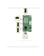
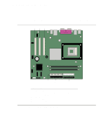
Intel Desktop Board D865GVHZ Product Guide Connecting Hardware Control and Power Cables Figure 10 shows the location of the chassis intrusion and fan headers, and power connectors. Chassis rear fan 1 12 V Processor core voltage connector 1 2 Processor fan 1 Chassis intrusion connector 1 Chassis front fan 1 Main power connector 2 1 OM17027 Figure 10. Location of Hardware Control Headers and Power Connectors 36
-
 1
1 -
2
-
3
-
4
-
5
-
6
-
7
-
8
-
9
-
10
-
11
-
12
-
13
-
14
-
15
-
16
-
17
-
18
-
19
-
20
-
21
-
22
-
23
-
24
-
25
-
26
-
27
-
28
-
29
-
30
-
 31
31 -
 32
32 -
 33
33 -
 34
34 -
 35
35 -
 36
36 -
 37
37 -
 38
38 -
 39
39 -
 40
40 -
 41
41 -
42
-
43
-
44
-
45
-
46
-
47
-
48
-
49
-
50
-
51
-
52
-
53
-
54
-
55
-
56
-
57
-
58
-
59
-
60
-
61
-
62
-
63
-
64
-
65
-
66
-
67
-
68
-
69
-
70
-
71
-
72
-
73
-
74
-
75
-
76
-
77
-
78
-
79
-
80
-
81
-
82
-
83
-
84
-
85
-
86
-
87
-
88
 |
 |

Intel Desktop Board D865GVHZ Product Guide
36
Connecting Hardware Control and Power Cables
Figure 10 shows the location of the chassis intrusion and fan headers, and power connectors.
OM17027
Processor
fan
1
Chassis
front fan
1
Chassis
rear fan
1
12 V
Processor core
voltage connector
1
Main power
connector
1
2
2
Chassis intrusion
1
connector
Figure 10.
Location of Hardware Control Headers and Power Connectors