Intel D945PLNM English Product Guide
Intel D945PLNM Manual
 |
View all Intel D945PLNM manuals
Add to My Manuals
Save this manual to your list of manuals |
Intel D945PLNM manual content summary:
- Intel D945PLNM | English Product Guide - Page 1
Intel® Desktop Board D945PLNM Product Guide Order Number: D40046-001 - Intel D945PLNM | English Product Guide - Page 2
Intel® Desktop Board D945PLNM Product Guide Date February 2006 If an FCC declaration of conformity marking is present on the board accordance with the instructions, may cause harmful Intel may make changes to specifications and product descriptions at any time, without notice. Desktop Board D945PLNM - Intel D945PLNM | English Product Guide - Page 3
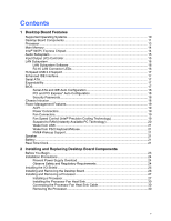
by Intel. Document Organization The chapters in this Product Guide are arranged as follows: 1 Desktop Board Features: a summary of product features 2 Installing and Replacing Desktop Board Components: instructions on how to install the desktop board and other hardware components 3 Updating the BIOS - Intel D945PLNM | English Product Guide - Page 4
Intel Desktop Board D945PLNM Product Guide Terminology The table below gives descriptions to some common terms used in the product guide. Term Description GB Gigabyte (1,073,741,824 bytes) GHz Gigahertz (one billion hertz) KB Kilobyte (1024 bytes) MB Megabyte (1,048,576 bytes) Mbit - Intel D945PLNM | English Product Guide - Page 5
Power Supply Overload 24 Observe Safety and Regulatory Requirements 24 Installing the I/O Shield ...25 Installing and Removing the Desktop Board 26 Installing and Removing a Processor 27 Installing a Processor 27 Installing the Processor Fan Heat Sink 30 Connecting the Processor Fan Heat Sink - Intel D945PLNM | English Product Guide - Page 6
Power Cables 44 Other Connectors...45 Setting the BIOS Configuration Jumper 46 Clearing Passwords ...47 Back Panel Connectors...48 3 Updating the BIOS Updating the BIOS with the Intel® Express BIOS Update Utility 55 Updating the BIOS with the Iflash Memory Update Utility 55 Obtaining the BIOS - Intel D945PLNM | English Product Guide - Page 7
Tables 1. Feature Summary...9 2. Desktop Board D945PLNM Components 12 3. Power Supply Requirements 13 4. Desktop Board D945PLNM Memory Configurations 14 5. LAN Connector LEDs ...16 6. Front Panel Audio Header Signal Names for Intel High Definition Audio 40 7. AC '97 Audio Header Signal Names 40 - Intel D945PLNM | English Product Guide - Page 8
Intel Desktop Board D945PLNM Product Guide viii - Intel D945PLNM | English Product Guide - Page 9
of the desktop board. Table 1. Feature Summary Form Factor Processor Main Memory Chipset microATX (243.84 millimeters [9.60 inches] x 243.84 millimeters [9.60 inches]) Support for an Intel® processor in the LGA775 package • Two 240-pin, 1.8 V SDRAM Dual Inline Memory Module (DIMM) sockets • 533 - Intel D945PLNM | English Product Guide - Page 10
about Desktop Board D945PLNM, including the Technical Product Specification (TPS), BIOS updates, and device drivers, go to: http://support.intel.com/support/motherboards/desktop/ Supported Operating Systems The desktop board supports the following operating systems: • Microsoft Windows* XP - Intel D945PLNM | English Product Guide - Page 11
Features Desktop Board Components Figure 1 shows the approximate location of the major components on Desktop Board D945PLNM. Line In A B C DE F G H V Intel® 82945 (MCH) Intel® U 82801 (ICH7) T I J Channel A, DIMM 0 Channel B, DIMM 0 S R Q PO N M L K Figure 1. Desktop Board D945PLNM - Intel D945PLNM | English Product Guide - Page 12
Alternate front panel power LED header Front panel header Hi-speed USB 2.0 headers Chassis intrusion header Speaker Related Links: Go to the following links for more information about: • Desktop Board D945PLNM • Supported processors • Audio software and utilities • LAN software and drivers http - Intel D945PLNM | English Product Guide - Page 13
power supply Desktop Board D945PLNM supports an Intel processor in the LGA775 package. Processors are not included with the desktop board and must be purchased separately. The processor connects to the desktop board through the LGA775 socket. The supported processors list for Desktop Board D945PLNM - Intel D945PLNM | English Product Guide - Page 14
Intel Desktop Board D945PLNM Product Guide Main Memory NOTE To be fully compliant with all applicable Intel® SDRAM memory specifications, the board should be populated with DIMMs that support the Serial Presence Detect (SPD) data structure. If your memory modules do not support SPD, you will see a - Intel D945PLNM | English Product Guide - Page 15
to the following link or pages for more information about: • Audio drivers and utilities http://support.intel.com/support/motherboards/desktop/ • Installing the front panel audio solution, page 40 in Chapter 2 • The location of audio connectors, Figure 21 on page 42 Input/Output (I/O) Controller The - Intel D945PLNM | English Product Guide - Page 16
http://support.intel.com/support/motherboards/desktop RJ-45 LAN Connector LEDs Two LEDs are built into the RJ-45 LAN connector located on the back panel (see Figure 2). AB OM19073 Figure 2. LAN Connector LEDs Table 5 describes the LED states when the board is powered up and the 10/100 Ethernet LAN - Intel D945PLNM | English Product Guide - Page 17
Serial ATA The desktop board supports four Serial ATA channels (3.0 Gb/s) via ICH7, connecting one device per channel. Expandability For system expansion, the desktop board provides the following: • One PCI Express x1 connector • Two PCI connectors BIOS The BIOS provides the Power-On Self-Test - Intel D945PLNM | English Product Guide - Page 18
Intel Desktop Board D945PLNM Product Guide Serial ATA and IDE Auto Configuration If you install a Serial ATA or IDE device (such as a hard drive) in your computer, the autoconfiguration utility in the BIOS automatically detects and configures the device for your computer. You do not need to run the - Intel D945PLNM | English Product Guide - Page 19
the desktop board BIOS. Disabling the processor fan speed control will result in the fan operating at full speed if it is not a self controlled fan. It is recommended that processor fan speed control remain enabled (default BIOS setting) when using the processor fan heat-sink included with Intel - Intel D945PLNM | English Product Guide - Page 20
Intel Desktop Board D945PLNM Product Guide Suspend to RAM (Instantly Available PC Technology) CAUTIONS For Instantly Available PC technology, the 5 V standby line for the power supply must be capable of delivering adequate +5 V standby current. Failure to provide adequate standby current when using - Intel D945PLNM | English Product Guide - Page 21
provides audible error code (beep code) information during the Power-On Self-Test (POST). Battery A battery on the desktop board keeps the values in CMOS RAM and the clock current when the computer is turned off. Go to page 49 for instructions on how to replace the battery. Real-Time Clock The - Intel D945PLNM | English Product Guide - Page 22
Intel Desktop Board D945PLNM Product Guide 22 - Intel D945PLNM | English Product Guide - Page 23
the desktop board • Install and remove a processor • Install and remove memory • Install and remove a PCI Express x16 card • Connect the IDE and Serial ATA cables • Connect to the internal headers • Connect to the flexible audio system • Connect to the chassis fan and power connectors • Set the BIOS - Intel D945PLNM | English Product Guide - Page 24
, and heat sinks) • Damage to wires that could cause a short circuit Observe all warnings and cautions that instruct you to refer computer servicing to qualified technical personnel. Prevent Power Supply Overload Do not overload the power supply output. To avoid overloading the power supply, make - Intel D945PLNM | English Product Guide - Page 25
transmissions, protects internal components from dust and foreign objects, and promotes correct airflow within the chassis. Install the I/O shield before installing the desktop board in the chassis. Place the shield inside the chassis as shown in Figure 4. Press the shield into place so that it fits - Intel D945PLNM | English Product Guide - Page 26
power before you open the computer can result in personal injury or equipment damage. Refer to your chassis manual for instructions on installing and removing the desktop board. Figure 5 shows the location of the eight mounting screw holes for Desktop Board D945PLNM. OM19076 Figure 5. Desktop Board - Intel D945PLNM | English Product Guide - Page 27
Replacing Desktop Board Components Installing and Removing a Processor Instructions on how to install the processor to the desktop board are given below. Installing a Processor CAUTION Before installing or removing the processor, make sure the AC power has been removed by unplugging the power cord - Intel D945PLNM | English Product Guide - Page 28
Intel Desktop Board D945PLNM Product Guide 4. Remove the plastic protective socket cover from the load plate (Figure 8, E). Do not discard the protective socket cover. Always replace the socket cover if the processor is removed from the socket. E OM19079 Figure 8. Remove the Protective Socket Cover - Intel D945PLNM | English Product Guide - Page 29
Installing and Replacing Desktop Board Components 6. Hold the processor with your thumb and index fingers oriented as shown in Figure 10. Make sure fingers align to the socket cutouts (Figure 10, F). Align notches (Figure 10, G) with the socket (Figure 10, H). Lower the processor straight down - Intel D945PLNM | English Product Guide - Page 30
Product Guide Installing the Processor Fan Heat Sink Desktop Board D945PLNM has an integrated processor fan heat sink retention mechanism (RM). For instructions on how to attach the processor fan heat sink to the integrated processor fan heat sink RM, refer to the boxed processor manual or the Intel - Intel D945PLNM | English Product Guide - Page 31
memory specifications, the board requires DIMMs that support the Serial Presence Detect (SPD) data structure. You can access the PC Serial Presence Detect Specification at: http://www.intel.com/technology/memory/ddr/specs/dda18c32_64_128x72ag_a.pdf The desktop board has two 240-pin DDR2 DIMM sockets - Intel D945PLNM | English Product Guide - Page 32
Intel Desktop Board D945PLNM Product Guide To make sure you have the correct DIMM, place it on the illustration of the DDR2 DIMM in Figure 14. All the notches should match with the DDR2 DIMM. DDR DDR2 mm 1 2 3 4 5 6 7 8 9 10 11 12 13 OM19085 Figure 14. Use DDR2 DIMMs 32 - Intel D945PLNM | English Product Guide - Page 33
Installing and Replacing Desktop Board Components Installing DIMMs To install a DIMM, follow these steps: 1. Observe the precautions in "Before You Begin" on page 23. 2. Turn off all peripheral devices connected to the computer. Turn off the computer and disconnect the AC power cord. 3. Remove the - Intel D945PLNM | English Product Guide - Page 34
Intel Desktop Board D945PLNM Product Guide Removing DIMMs To remove a DIMM, follow these steps: 1. Observe the precautions in "Before You Begin" on page 23. 2. Turn off all peripheral devices connected to the computer. Turn off the computer. 3. Remove the AC power cord from the computer. 4. Remove - Intel D945PLNM | English Product Guide - Page 35
Express connector pins. Depending on the over-current protection of the power supply, certain desktop board components and/or traces may be damaged. Installing a PCI Express metal bracket to the chassis back panel with a screw (Figure 16, B). B A OM19098 Figure 16. Installing a PCI Express x16 Card - Intel D945PLNM | English Product Guide - Page 36
Intel Desktop Board D945PLNM Product Guide Removing the PCI Express x16 Card Follow these instructions to remove the PCI Express x16 card from the RM: 1. Observe the precautions in "Before You Begin" on page 23. 2. Remove the screw (Figure 17, A) - Intel D945PLNM | English Product Guide - Page 37
desktop board. The cable supports the ATA-66/100 transfer protocol. Figure 18 shows the correct installation of the cable. NOTES ATA-66/100 compatible cables are backward compatible the cable end with the single connector (blue) to the Intel desktop board (Figure 18, A). • Attach the cable end with - Intel D945PLNM | English Product Guide - Page 38
Intel Desktop Board D945PLNM Product Guide Connecting the Serial ATA (SATA) Cable The SATA cable (4-conductor) supports the Serial ATA protocol and connects a single drive to the desktop board. For correct cable function: 1. Observe the precaution in "Before You Begin" on page 23. 2. Attach the - Intel D945PLNM | English Product Guide - Page 39
Desktop Board Power - LED + 4 2 3 1 - HD LED + C -3 +1 Alternate Front Panel Power LED B Power (+5 V) 1 2 Power (+5 V) D- 3 4 D- D+ 5 6 D+ Ground 7 8 Ground Key (no pin) 10 No Connection Item A B C D Description Front panel audio USB 2.0 Alternate front panel power LED Front panel - Intel D945PLNM | English Product Guide - Page 40
Intel Desktop Board D945PLNM Product Guide Installing a Front Panel Audio Solution for Intel® High Definition Audio Figure 20, A on page 39 shows the location of the yellow front panel audio header. Table 6 shows the pin assignments for the front panel audio header. Table 6. Front Panel Audio - Intel D945PLNM | English Product Guide - Page 41
Installing and Replacing Desktop Board Components Connecting to the USB 2.0 Header Before Pin 2 4 6 GND 10 USB Port B Signal Name POWER DD+ Ground NO CONNECT Connecting to the Front Panel Header Before connecting to the front panel header, observe the precautions in "Before You Begin" on page - Intel D945PLNM | English Product Guide - Page 42
Intel Desktop Board D945PLNM Product Guide Connecting to the Flexible Audio System After installing the SigmaTel audio driver from the Intel Express Installer driver CD-ROM, the multi-channel audio feature can be enabled. Figure 21 shows the back panel audio connectors. The default connector - Intel D945PLNM | English Product Guide - Page 43
Installing and Replacing Desktop Board Components Connecting Chassis Fan and Power Cables Connecting Chassis Fan Cables Connect the chassis fan cables to the 3-pin fan headers on the desktop board. Figure 22 shows the location of the fan headers. 321 321 32 1 Figure 22. Location of Chassis Fan - Intel D945PLNM | English Product Guide - Page 44
Intel Desktop Board D945PLNM Product Guide Connecting Power Cables CAUTION Failure to use the appropriate power supply and/or not connecting the 12 V (2 x 2 pin) power connector to the desktop board may result in damage to the board or the system may not function properly. See Table 3 on page 13 for - Intel D945PLNM | English Product Guide - Page 45
Other Connectors Figure 24 shows the location of the other connectors on the desktop board. ABC E D Item Description A PCI Express x1 connector B PCI bus add-in card connector 2 C PCI bus add-in card connector 1 D Diskette drive connector E Chassis intrusion connector - Intel D945PLNM | English Product Guide - Page 46
Intel Desktop Board D945PLNM Product Guide Setting the BIOS Configuration Jumper NOTE Always turn off the power and unplug the power cord from the computer before moving the jumper. Moving the jumper with the power on may result in unreliable computer operation. Figure 25 shows the location of the - Intel D945PLNM | English Product Guide - Page 47
Installing and Replacing Desktop Board Components Clearing Passwords This procedure assumes that the board is installed in values and exit Setup. 10. Turn off the computer. Disconnect the computer's power cord from the AC power source. 11. Remove the computer cover. 12. To restore normal operation, - Intel D945PLNM | English Product Guide - Page 48
Intel Desktop Board D945PLNM Product Guide Back Panel Connectors NOTE The line out connector, located on the back panel, is designed to power either headphones or amplified speakers only. Poor audio quality may occur if passive (non-amplified) speakers are connected to this output. Figure 26 shows - Intel D945PLNM | English Product Guide - Page 49
Desktop Board Components Replacing the Battery A coin-cell battery (CR2032) powers the real-time clock and CMOS memory. When the computer is not plugged into a wall socket, the battery has an estimated life of three years. When the computer is plugged in, the standby current from the power supply - Intel D945PLNM | English Product Guide - Page 50
Intel Desktop Board D945PLNM Product Guide PRECAUCIÓN Existe peligro de explosión si la pila no se cambia de forma adecuada. Utilice solamente pilas iguales o del mismo tipo que las recomendadas por - Intel D945PLNM | English Product Guide - Page 51
Installing and Replacing Desktop Board Components OSTRZEŻENIE Istnieje niebezpieczeństwo wybuchu w przypadku zastosowania niewłaściwego typu baterii. Zużyte baterie należy w miarę możliwości utylizować zgodnie z odpowiednimi przepisami - Intel D945PLNM | English Product Guide - Page 52
Intel Desktop Board D945PLNM Product Guide 52 - Intel D945PLNM | English Product Guide - Page 53
and Replacing Desktop Board Components To replace the battery, follow these steps: 1. Observe the precautions in "Before You Begin" (see page 23). 2. Turn off all peripheral devices connected to the computer. Disconnect the computer's power cord from the AC power source (wall outlet or power adapter - Intel D945PLNM | English Product Guide - Page 54
Intel Desktop Board D945PLNM Product Guide 54 - Intel D945PLNM | English Product Guide - Page 55
. To update the BIOS with the Intel Express BIOS Update utility: 1. Go to the Intel World Wide Web site: http://support.intel.com/support/motherboards/desktop/ 2. Navigate to the D945PLNM page, click "[view] Latest BIOS updates," and select the Express BIOS Update utility file. 3. Download the file - Intel D945PLNM | English Product Guide - Page 56
to the Desktop Board D945PLNM page on the Intel World Wide Web site at: http://support.intel.com/support/motherboards/desktop Navigate to the D945PLNM page, click "[view] Latest BIOS updates," and select the Iflash BIOS Update utility file. NOTE Review the instructions distributed with the - Intel D945PLNM | English Product Guide - Page 57
Error Messages and Indicators Desktop Board D945PLNM reports POST errors in two ways: • By sounding a beep code • By displaying an error message on the monitor BIOS Beep Codes The BIOS also issues a beep code (one long tone followed by two short tones) during POST if the video configuration fails - Intel D945PLNM | English Product Guide - Page 58
Intel Desktop Board D945PLNM Product Guide 58 - Intel D945PLNM | English Product Guide - Page 59
statements • Electromagnetic Compatibility (EMC) regulations • Product certifications Safety Regulations Desktop Board D945PLNM complies with the Place Battery Marking There is insufficient space on this desktop board to provide instructions for replacing and disposing of the Lithium ion coin - Intel D945PLNM | English Product Guide - Page 60
Intel Desktop Board D945PLNM Product Guide European Union Declaration of Conformity Statement We, Intel Corporation, declare under our sole responsibility that the product Intel® Desktop Board D945PLNM is in conformity with all applicable essential requirements necessary for CE marking, following - Intel D945PLNM | English Product Guide - Page 61
the scope of covered products, available locations, shipping instructions, terms and conditions, etc Intel Product Recycling Program http://www.intel.com/intel/other/ehs/product_ecology/Recycling_Program.htm Deutsch Als Teil von Intels Engagement für den Umweltschutz hat das Unternehmen das - Intel D945PLNM | English Product Guide - Page 62
Intel Desktop Board D945PLNM Product Guide Français Dans le cadre de son engagement pour la protection de l'environnement, Intel a mis en œuvre le programme Intel Product Recycling Program (Programme de recyclage des produits Intel) pour permettre aux consommateurs de produits Intel de recycler les - Intel D945PLNM | English Product Guide - Page 63
ayrıntılarını ögrenmek için lütfen http://www.intel.com/intel/other/ehs/product_ecology/Recycling_Program.htm web sayfasına gidin. Lead-Free Desktop Board This desktop board is lead free although certain discrete components used on the board contain a small amount of lead which is necessary for - Intel D945PLNM | English Product Guide - Page 64
Intel Desktop Board D945PLNM Product Guide EMC Regulations Desktop Board D945PLNM complies with the EMC regulations stated in Table 15 when correctly installed in a compatible Install and use the equipment according to the instruction manual. Korean Class B statement translation: This is household - Intel D945PLNM | English Product Guide - Page 65
MIC (Ministry of Information and Communication) mark. Includes adjacent MIC certification number: CPU-D945PLNM. For information about MIC certification, go to http://support.intel.com/support/motherboards/desktop/ Taiwan BSMI (Bureau of Standards, Metrology and Inspections) mark. Includes adjacent - Intel D945PLNM | English Product Guide - Page 66
Intel Desktop Board D945PLNM Product Guide Chassis and Component Certifications Ensure that the chassis and certain components; such as the power supply . Wiring and cables must also be UL listed or recognized and suitable for the intended use front of this product guide demonstrates compliance with
-
 1
1 -
 2
2 -
 3
3 -
 4
4 -
 5
5 -
 6
6 -
 7
7 -
8
-
9
-
10
-
11
-
12
-
13
-
14
-
15
-
16
-
17
-
18
-
19
-
20
-
21
-
22
-
23
-
24
-
25
-
26
-
27
-
28
-
29
-
30
-
31
-
32
-
33
-
34
-
35
-
36
-
37
-
38
-
39
-
40
-
41
-
42
-
43
-
44
-
45
-
46
-
47
-
48
-
49
-
50
-
51
-
52
-
53
-
54
-
55
-
56
-
57
-
58
-
59
-
60
-
61
-
62
-
63
-
64
-
65
-
66
 |
 |

Intel
®
Desktop Board D945PLNM
Product Guide
Order Number:
D4004
6
-001