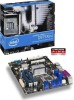
Intel D975XBX2KR Product Guide
Intel D975XBX2KR - Core 2 Duo Ready Socket 775 ATX Motherboard Manual
 |
UPC - 735858186162
View all Intel D975XBX2KR manuals
Add to My Manuals
Save this manual to your list of manuals |
Intel D975XBX2KR manual content summary:
- Intel D975XBX2KR | Product Guide - Page 1
Intel® Desktop Board D975XBX2 Product Guide Order Number: D63326-005 - Intel D975XBX2KR | Product Guide - Page 2
of the Intel® Desktop Board D975XBX2 Product Guide Update to the Intel® Desktop Board D975XBX2 Product Guide Update to the Intel® Desktop Board D975XBX2 Product Guide Update to the Intel® Desktop Board D975XBX2 Product Guide Update to the Intel® Desktop Board D975XBX2 Product Guide September 2006 - Intel D975XBX2KR | Product Guide - Page 3
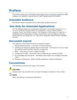
Guide gives information about board layout, component installation, BIOS updates, and regulatory requirements for Intel® Desktop Board D975XBX2. Intended Audience The Product Guide is intended only for technically qualified personnel. Use Only for Intended Applications All Intel desktop boards - Intel D975XBX2KR | Product Guide - Page 4
driver CD-ROM • Intel Express Installer software DVD-ROM • One diskette with the Intel® Matrix Storage RAID driver • One diskette with the Marvell* SATA Controller RAID driver • Back panel audio covers • Quick Reference poster • Integration Guide poster • Printed Product Guide • Configuration - Intel D975XBX2KR | Product Guide - Page 5
11 Desktop Board Components 12 Processor ...14 Main Memory...14 Intel® 975X Express Chipset 15 Audio Subsystem 16 Input/Output (I/O) Controller 16 LAN Subsystem 17 LAN Subsystem Software 17 RJ-45 LAN Connector LEDs 17 Hi-Speed USB 2.0 Support 18 Enhanced IDE Interface 18 Serial ATA...18 - Intel D975XBX2KR | Product Guide - Page 6
59 Updating the BIOS 59 Updating the BIOS with the Intel® Express BIOS Update Utility 59 Updating the BIOS with the Iflash Memory Update Utility 60 4 Configuring for RAID Requires Microsoft Windows* XP, Windows Vista*, or Windows 2000 and SATA Hard Drive(s) Configuring for RAID using Intel - Intel D975XBX2KR | Product Guide - Page 7
the Rear Panel USB 2.0 Adapter 47 26. Connecting an External Serial ATA Adapter 48 27. Location of Fan Headers 49 28. Connecting Power Supply Cables 50 29. Location of Other Connectors 51 30. Location of the BIOS Configuration Jumper Block 52 31. Back Panel Connectors 54 32. Removing - Intel D975XBX2KR | Product Guide - Page 8
Intel Desktop Board D975XBX2 Product Guide Tables 1. Feature Summary 9 2. Desktop Board D975XBX2 Components 13 3. Memory Operating Frequencies 15 4. RJ-45 10/100/1000 Gigabit Ethernet LAN Connector LEDs 17 5. Front Panel Header Signal Names 45 6. IEEE 1394a Header Signal Names - Intel D975XBX2KR | Product Guide - Page 9
briefly describes the main features of Intel® Desktop Board D975XBX2. Table 1 summarizes the major features of the desktop board. Table 1. Feature Summary Form Factor Processor Main Memory Chipset Graphics Audio Expansion Capabilities LAN Support BIOS RAID ATX (304.80 millimeters [12.00 inches - Intel D975XBX2KR | Product Guide - Page 10
fan speed control • Voltage sensing to detect out of range values Related Links For more information about Intel Desktop Board D975XBX2, including the Technical Product Specification (TPS), BIOS updates, and device drivers, go to: http://support.intel.com/support/motherboards/desktop/ 10 - Intel D975XBX2KR | Product Guide - Page 11
Desktop Board Features Supported Operating Systems The desktop board supports the following operating systems: • Microsoft Windows Vista* Ultimate • Microsoft Windows Vista Enterprise • Microsoft Windows Vista Business • Microsoft Windows Vista Home Premium • Microsoft Windows Vista Home Basic • - Intel D975XBX2KR | Product Guide - Page 12
Intel Desktop Board D975XBX2 Product Guide Desktop Board Components Figure 1 shows the approximate location of the major components on Desktop Board D975XBX2. Figure 1. Desktop Board D975XBX2 Components 12 - Intel D975XBX2KR | Product Guide - Page 13
4, compatible with external Serial ATA adapter (red) Front panel header Speaker Related Links Go to the following links for more information about: • Desktop Board D975XBX2 http://www.intel.com/design/motherbd http://support.intel.com/support/motherboards/desktop • Supported processors http - Intel D975XBX2KR | Product Guide - Page 14
connects to the Intel desktop board through the LGA775 socket. The supported processors list for Desktop Board D975XBX2 is located on the web at: http://support.intel.com/support/motherboards/desktop/ Related Links Go to the following links or pages for more information about: • Instructions - Intel D975XBX2KR | Product Guide - Page 15
memory, http://support.intel.com/support/motherboards/desktop/ • SDRAM specifications, http://www.intel.com/technology/memory/ • Installing memory, page 34 in Chapter 2 Intel® 975X Express Chipset The Intel 975X Express Chipset consists of the following devices: • Intel 82975X Memory Controller - Intel D975XBX2KR | Product Guide - Page 16
to the following link or pages for more information about audio drivers and utilities: http://support.intel.com/support/motherboards/desktop/ Input/Output (I/O) Controller The super I/O controller features the following: • One serial port • One parallel port with Extended Capabilities Port (ECP) and - Intel D975XBX2KR | Product Guide - Page 17
RJ-45 connector with status indicator LEDs • Configurable EEPROM that contains the MAC address LAN Subsystem Software For LAN software and drivers, refer to the D975XBX2 link on Intel's World Wide Web site at: http://support.intel.com/support/motherboards/desktop RJ-45 LAN Connector LEDs Two LEDs - Intel D975XBX2KR | Product Guide - Page 18
(such as CD-ROM drives) • Older PIO Mode devices • Ultra DMA-33 and ATA-66/100 protocols Serial ATA The desktop board supports eight Serial ATA channels, connecting one device per channel in either a RAID or a non-RAID configuration. Expandability For system expansion, the desktop board supports the - Intel D975XBX2KR | Product Guide - Page 19
desktop board, the auto-configuration utility in the BIOS automatically detects and configures the device for your computer. You do not need to run the BIOS Setup program after installing a Serial ATA or IDE device. You can override the auto-configuration options by specifying manual configuration - Intel D975XBX2KR | Product Guide - Page 20
system that provides full ACPI support. Fan Connectors Desktop Board D975XBX2 has four chassis fan connectors (three 3-pin and one 4-pin), and one processor fan connector (4-pin). Fan Speed Control (Intel® Precision Cooling Technology) Intel Precision Cooling Technology automatically adjusts - Intel D975XBX2KR | Product Guide - Page 21
(ACPI S3 sleep state) configuration. If the standby current necessary to support multiple wake events from the PCI and/or USB buses exceeds power supply capacity, the desktop board may lose register settings stored in memory. Instantly Available PC technology enables the board to enter the ACPI S3 - Intel D975XBX2KR | Product Guide - Page 22
Intel Desktop Board D975XBX2 Product Guide Resume on Ring The operation of Resume on Ring can be summarized for correct operation Wake from USB NOTE Wake from USB requires the use of a USB peripheral that supports Wake from USB. USB bus activity wakes the computer from an ACPI S1 or S3 state. Wake - Intel D975XBX2KR | Product Guide - Page 23
on the desktop board. The speaker provides audible error code (beep code) information during the Power-On Self-Test (POST). Battery A battery on the desktop board keeps the values in CMOS RAM and the clock current when the computer is turned off. See Chapter 2 starting on page 25 for instructions on - Intel D975XBX2KR | Product Guide - Page 24
Intel Desktop Board D975XBX2 Product Guide 24 - Intel D975XBX2KR | Product Guide - Page 25
• Install and remove the desktop board • Install and remove a processor • Install and remove memory • Install and remove a PCI Express x16 add-in card • Connect the IDE and Serial ATA cables • Connect internal headers • Install USB/external Serial ATA adapters • Connect chassis fan and power supply - Intel D975XBX2KR | Product Guide - Page 26
Intel Desktop Board D975XBX2 Product Guide Installation Precautions When you install and test the Intel desktop board, observe all warnings and cautions in the installation instructions. To avoid injury, be careful of: • Sharp pins on connectors • Sharp pins on printed circuit assemblies • Rough - Intel D975XBX2KR | Product Guide - Page 27
transmissions, protects internal components from dust and foreign objects, and promotes correct airflow within the chassis. Install the I/O shield before installing the desktop board in the chassis. Place the shield inside the chassis as shown in Figure 5. Press the shield into place so that it fits - Intel D975XBX2KR | Product Guide - Page 28
Intel Desktop Board D975XBX2 Product Guide Installing and Removing the Desktop Board CAUTION Only qualified technical personnel should do this procedure. Disconnect the computer from its power source before performing the procedures described here. Failure to disconnect - Intel D975XBX2KR | Product Guide - Page 29
Installing and Replacing Desktop Board Components Figure 6 shows the location of the 10 mounting screw holes for Desktop Board D975XBX2. Figure 6. Location of Mounting Screw Holes 29 - Intel D975XBX2KR | Product Guide - Page 30
Intel Desktop Board D975XBX2 Product Guide Installing and Removing a Processor Instructions on how to install the processor on the desktop board are given below. Installing a Processor CAUTION Before installing or removing the processor, make sure that AC power has been removed by unplugging the - Intel D975XBX2KR | Product Guide - Page 31
Replacing Desktop Board Components 4. Remove the protective socket cover from the load plate (Figure 9). Do not discard the protective socket cover. Always replace the socket cover if the processor is removed from the socket. Figure 9. Remove the Protective Socket Cover 5. Remove the processor from - Intel D975XBX2KR | Product Guide - Page 32
Intel Desktop Board D975XBX2 Product Guide 6. Hold the processor with your thumb and index fingers oriented as shown in Figure 11. Make sure fingers align to the socket cutouts (Figure 11, A) Align notches (Figure 11, B) with the socket (Figure 11, C). Lower the processor straight down without - Intel D975XBX2KR | Product Guide - Page 33
Installing the Processor Fan Heat Sink Desktop Board D975XBX2 has an integrated processor fan heat sink retention mechanism (RM). For instructions on how to attach the processor fan heat sink to the integrated processor fan heat sink RM, refer to the boxed processor manual or the Intel World Wide - Intel D975XBX2KR | Product Guide - Page 34
Intel Desktop Board D975XBX2 Product Guide Installing and Removing Memory Desktop Board D975XBX2 has four 240-pin DIMM sockets arranged as DIMM 0 and DIMM 1 in both Channel A and Channel B, as shown in Figure 18. Guidelines for Dual Channel Memory Configuration Before installing DIMMs, read and - Intel D975XBX2KR | Product Guide - Page 35
Installing and Replacing Desktop Board Components Three DIMMs Install a matched pair of DIMMs equal in speed and size in DIMM 0 ( DIMM 0 or DIMM 1 of channel B (see Figure 16). Figure 16. Dual Channel Memory Configuration Example 3 NOTE All other memory configurations will result in single channel - Intel D975XBX2KR | Product Guide - Page 36
Intel Desktop Board D975XBX2 Product Guide Installing DIMMs CAUTION Install memory in the DIMM sockets before installing a PCI Express x16 card to avoid interference with the memory retention mechanism. To make sure you have the correct DIMM, place it on the illustration of the DDR2 DIMM in Figure - Intel D975XBX2KR | Product Guide - Page 37
and Replacing Desktop Board Components Figure 18. Installing a DIMM 5. Make sure the clips at either end of the DIMM socket(s) are pushed outward to the open position. 6. Holding the DIMM by the edges, remove it from its anti-static package. 7. Position the DIMM above the socket. Align the - Intel D975XBX2KR | Product Guide - Page 38
Intel Desktop Board D975XBX2 Product Guide Removing DIMMs To remove a memory module, follow these steps: 1. Observe the precautions in "Before You Begin" on page 25. 2. Turn off all peripheral devices connected to the computer. Turn off the computer. 3. Remove the AC power cord from the computer. 4. - Intel D975XBX2KR | Product Guide - Page 39
Installing and Replacing Desktop Board Components Installing a PCI Express x16 Card If you are installing a single PCI Express Graphics card, install it in PCI Express connector 1 (see Figure 19, A) for - Intel D975XBX2KR | Product Guide - Page 40
Intel Desktop Board D975XBX2 Product Guide Follow these instructions to install any PCI Express x16 card: 1. completely seated in the connector and the card retention notch snaps into place around the RM pin. 3. Secure the card's metal bracket to the chassis back panel with a screw (Figure 20, - Intel D975XBX2KR | Product Guide - Page 41
Installing and Replacing Desktop Board Components Removing the PCI Express x16 Card Follow these instructions to remove the PCI Express x16 card from the RM: 1. Observe the precautions in "Before You Begin" on page 25. 2. Remove the screw that secures - Intel D975XBX2KR | Product Guide - Page 42
Intel Desktop Board D975XBX2 Product Guide Connecting the IDE Cable The IDE cable can be used to connect two drives to the desktop board. The cable supports the ATA-66/100 transfer protocol. Figure 22 shows the correct installation of the cable. NOTE ATA-66/100 compatible cables are backward - Intel D975XBX2KR | Product Guide - Page 43
Installing and Replacing Desktop Board Components Connecting the Serial ATA Cable The SATA cable (4-conductor) supports the Serial ATA protocol and connects a single drive to the desktop board. Either end of the cable can be connected to the SATA drive or the connector on the board. For correct - Intel D975XBX2KR | Product Guide - Page 44
Intel Desktop Board D975XBX2 Product Guide Connecting Internal Headers Before connecting cables to the internal headers, observe the precautions in "Before You Begin" on page 25. Item A B C D E Description Front panel Alternate front panel power LED IEEE 1394a USB 2.0 Front panel audio Figure 24. - Intel D975XBX2KR | Product Guide - Page 45
Desktop Board Components Front Panel Header Figure 24, A on page 44 shows the location of the multi-colored front panel header. Table 5 shows the pin assignments for the front panel header. Table 5. Front Panel Header Signal Names Pin Description In/Out Pin Connected 9 Power Out 10 No pin In - Intel D975XBX2KR | Product Guide - Page 46
Intel Desktop Board D975XBX2 Product Guide USB 2.0 Headers See Figure 24, D for the location of the black USB 2.0 headers. Table 7 shows the pin assignments for the headers. Table 7. USB 2.0 Header Signal Names USB Port A Pin Signal Name Pin 1 Power (+5V) 2 3 D- 4 5 D+ 6 7 Ground 8 - Intel D975XBX2KR | Product Guide - Page 47
Panel USB 2.0 Adapter Follow these instructions to install the rear panel USB 2.0 adapter (see Figure 25): 1. Observe the precautions in "Before You Begin" on page 25. 2. Attach the connector at the end of the adapter cable to the USB 2.0 header on the desktop board. 3. Secure the metal bracket at - Intel D975XBX2KR | Product Guide - Page 48
Intel Desktop Board D975XBX2 Product Guide Installing an External Serial ATA Adapter If you are installing an external Serial ATA (eSATA) adapter to the desktop motherboard, follow these instructions (see Figure 26): 1. Observe the precautions in "Before You Begin" on page 25. 2. Attach the - Intel D975XBX2KR | Product Guide - Page 49
Installing and Replacing Desktop Board Components Connecting Chassis Fan Cables Connect the chassis fan cables to the desktop board fan headers shown in Figure 27. Figure 27. Location of Fan Headers 49 - Intel D975XBX2KR | Product Guide - Page 50
Intel Desktop Board D975XBX2 Product Guide Connecting Power Supply Cables NOTE Failure to use the appropriate power supply and/or not connecting the 12 V (2x4) power connector to the desktop board may result in damage to the board or the system may not function properly. The 2x12 main power - Intel D975XBX2KR | Product Guide - Page 51
2x2 to 2x4 adapter when using an Intel® Pentium® processor Extreme Edition or a processor that is not running at its default settings. Doing so may result in damage to the desktop board. 3. Connect the 1x4 power supply cable to the 1x4 connector. 4. Connect the main power supply cable to the 2x12 - Intel D975XBX2KR | Product Guide - Page 52
Intel Desktop Board D975XBX2 Product Guide Setting the BIOS Configuration Jumper CAUTION Always turn off the power and unplug the power cord from the computer before changing the jumper. Moving the jumper with the power on may result in unreliable computer operation. Figure 30 shows the location of - Intel D975XBX2KR | Product Guide - Page 53
and Replacing Desktop Board Components Clearing Passwords This procedure assumes that the board is installed in the computer and the configuration jumper block is set to normal mode. 1. Observe the precautions in "Before You Begin" on page 25. 2. Turn off all peripheral devices connected to the - Intel D975XBX2KR | Product Guide - Page 54
Intel Desktop Board D975XBX2 Product Guide Back Panel Connectors NOTE The line out connector, located on the back panel, is designed to power either headphones or amplified speakers only. Poor audio quality may occur if passive (nonamplified) speakers are connected to this output. Figure 31 shows - Intel D975XBX2KR | Product Guide - Page 55
Desktop Board Components Replacing the Battery A coin-cell battery (CR2032) powers the real-time clock and CMOS memory. When the computer is not plugged into a wall socket voltage drops below a certain level, the BIOS Setup program settings stored in CMOS RAM (for example, the date and time) might - Intel D975XBX2KR | Product Guide - Page 56
Intel Desktop Board D975XBX2 Product Guide VORSICHT Bei falschem Einsetzen einer neuen Batterie besteht Explosionsgefahr. Die Batterie darf nur durch denselben oder einen entsprechenden, vom Hersteller empfohlenen Batterietyp ersetzt werden. Entsorgen - Intel D975XBX2KR | Product Guide - Page 57
Installing and Replacing Desktop Board Components VIGYAZAT Ha a telepet nem a megfelelő típusú telepre cseréli, az felrobbanhat. A telepeket lehetőség szerint újra kell hasznosítani. A használt telepeket a helyi környezetvédelmi - Intel D975XBX2KR | Product Guide - Page 58
Intel Desktop Board D975XBX2 Product Guide UYARI Yanlış türde pil takıldığında patlama riski vard devices connected to the computer. Disconnect the computer's power cord from the AC power source (wall outlet or power adapter). 3. Remove the computer cover. 4. Locate the battery on the board (see - Intel D975XBX2KR | Product Guide - Page 59
of the Intel® Flash Memory Update Utility and the ease-of use of Windows-based installation wizards. To update the BIOS with the Intel Express BIOS Update utility: 1. Go to the Intel World Wide Web site: http://support.intel.com/support/motherboards/desktop/ 2. Navigate to the D975XBX2 page, click - Intel D975XBX2KR | Product Guide - Page 60
update file contains: • New BIOS files • BIOS recovery files • Intel Flash Memory Update Utility You can obtain the BIOS update file through your computer supplier or by navigating to the Desktop Board D975XBX2 page on the Intel World Wide Web site at: http://support.intel.com/support/motherboards - Intel D975XBX2KR | Product Guide - Page 61
Remove the computer cover and locate the configuration jumper block (see Figure 30). 3. Remove the jumper from all pins as shown below to set recovery mode for Setup. 4. Insert the bootable BIOS update diskette into diskette drive A. 5. Replace the computer cover, connect the power cord, turn on the - Intel D975XBX2KR | Product Guide - Page 62
Intel Desktop Board D975XBX2 Product Guide 62 - Intel D975XBX2KR | Product Guide - Page 63
for RAID Requires Microsoft Windows* XP, Windows Vista*, or Windows 2000 and SATA Hard Drive(s) Configuring for RAID using Intel® Matrix Storage Technology Configuring the BIOS 1. Assemble your system and attach two or more SATA hard drives to the black SATA connectors. 2. Enter system BIOS Setup - Intel D975XBX2KR | Product Guide - Page 64
Intel® 82801GH SATA RAID Controller driver. 3. Finish the Windows installation and install all necessary drivers. 4. Install the Intel Matrix Storage Console software via the Intel Express Installer CD included with your desktop board or after downloading it from the Internet at http://support.intel - Intel D975XBX2KR | Product Guide - Page 65
the Windows installation CD. 2. At the beginning of Windows Setup, press to install a third-party SCSI or RAID driver. When prompted, insert the diskette labeled Marvell Storage Technology RAID Driver. Install the Marvell 88SE61XX SATA RAID Controller driver. 3. Finish the Windows installation - Intel D975XBX2KR | Product Guide - Page 66
Intel Desktop Board D975XBX2 Product Guide 66 - Intel D975XBX2KR | Product Guide - Page 67
does not properly checksum to zero. Table 10. Beep Codes Beep 3 Siren Description No memory Processor overheat (on reboot) BIOS Error Messages When a recoverable error occurs during the POST, the BIOS displays an error message describing the problem. Table 11. BIOS Error Messages Error Message - Intel D975XBX2KR | Product Guide - Page 68
Intel Desktop Board D975XBX2 Product Guide 68 - Intel D975XBX2KR | Product Guide - Page 69
statements • Electromagnetic Compatibility (EMC) regulations • Product certifications Safety Regulations Desktop Board D975XBX2 complies with the Place Battery Marking There is insufficient space on this desktop board to provide instructions for replacing and disposing of the Lithium ion coin - Intel D975XBX2KR | Product Guide - Page 70
Intel Desktop Board D975XBX2 Product Guide European Union Declaration of Conformity Statement We, Intel Corporation, declare under our sole responsibility that the product Intel® Desktop Board D975XBX2 is in conformity with all applicable essential requirements necessary for CE marking, following - Intel D975XBX2KR | Product Guide - Page 71
the http://www.intel.com/intel/other/ehs/product_ecology/Recycling_Program.htm for the details of this program, including the scope of covered products, available locations, shipping instructions, terms and conditions, etc. Intel Product Recycling Program http://www.intel.com/intel/other/ehs - Intel D975XBX2KR | Product Guide - Page 72
Intel Desktop Board D975XBX2 Product Guide Deutsch Als Teil von Intels Engagement für den Umweltschutz hat das Unternehmen das Intel Produkt-Recyclingprogramm implementiert, das Einzelhandelskunden von Intel Markenprodukten ermöglicht, gebrauchte Produkte an ausgewählte Standorte für ordnungsgemäßes - Intel D975XBX2KR | Product Guide - Page 73
locais disponíveis, as instruções de envio, os termos e condições, etc. Russian Intel Intel (Product Recycling Program Intel http://www.intel.com/intel/other/ehs/product_ecology/Recycling_Program.htm Türkçe Intel, çevre sorumluluğuna bağımlılığının bir parçası olarak, perakende tüketicilerin - Intel D975XBX2KR | Product Guide - Page 74
Intel Desktop Board D975XBX2 Product Guide Lead-Free Desktop Board This desktop board is lead free although certain discrete components used on the board contain a small amount of lead which is necessary for component performance and/or reliability. This desktop board is referred to as "Lead-free - Intel D975XBX2KR | Product Guide - Page 75
Regulatory Compliance EMC Regulations Desktop Board D975XBX2 complies with the EMC regulations stated in Table 14 when correctly installed in a compatible host system. Table 14. EMC Regulations Regulation FCC Class B ICES-003 (Class B) EN55022: 1998 (Class B) EN55024: 1998 AS/NZS CISPR22 (Class - Intel D975XBX2KR | Product Guide - Page 76
Intel Desktop Board D975XBX2 Product Guide Japanese Kanji statement translation: This is a Class B product based on the standard of the Voluntary Control Council for Interference from Information Technology Equipment (VCCI). If this is used near a radio or television receiver in a domestic - Intel D975XBX2KR | Product Guide - Page 77
number: CPU-D975XBX2. For information about MIC certification, go to http://support.intel.com/support/motherboards/desktop/ Taiwan BSMI (Bureau of Standards, Metrology and Inspections) mark. Includes adjacent Intel company number, D33025. Printed wiring board manufacturer's recognition - Intel D975XBX2KR | Product Guide - Page 78
Intel Desktop Board D975XBX2 Product Guide Chassis and Component Certifications Ensure that the chassis and certain components; such as the power with safety requirements. The Industry Canada statement at the front of this product guide demonstrates compliance with Canadian EMC regulations. 78
-
 1
1 -
 2
2 -
 3
3 -
 4
4 -
 5
5 -
 6
6 -
 7
7 -
8
-
9
-
10
-
11
-
12
-
13
-
14
-
15
-
16
-
17
-
18
-
19
-
20
-
21
-
22
-
23
-
24
-
25
-
26
-
27
-
28
-
29
-
30
-
31
-
32
-
33
-
34
-
35
-
36
-
37
-
38
-
39
-
40
-
41
-
42
-
43
-
44
-
45
-
46
-
47
-
48
-
49
-
50
-
51
-
52
-
53
-
54
-
55
-
56
-
57
-
58
-
59
-
60
-
61
-
62
-
63
-
64
-
65
-
66
-
67
-
68
-
69
-
70
-
71
-
72
-
73
-
74
-
75
-
76
-
77
-
78
 |
 |

Intel
®
Desktop Board D975XBX2
Product Guide
Order Number:
D63326-005