Intel DG35EC Product Guide
Intel DG35EC - Desktop Board Classic Series Motherboard Manual
 |
UPC - 735858200448
View all Intel DG35EC manuals
Add to My Manuals
Save this manual to your list of manuals |
Intel DG35EC manual content summary:
- Intel DG35EC | Product Guide - Page 1
Intel® Desktop Board DG35EC Product Guide Order Number: E30452-001 - Intel DG35EC | Product Guide - Page 2
Intel® Desktop Board DG35EC Product Guide Date February 2008 If an FCC declaration of conformity marking is present on the board in accordance with the instructions, may cause harmful Intel may make changes to specifications and product descriptions at any time, without notice. Desktop Board DG35EC - Intel DG35EC | Product Guide - Page 3
Installing and Replacing Desktop Board Components: instructions on how to install the Desktop Board and other hardware components 3 Updating the BIOS: instructions on how to update the BIOS A Error Messages and Indicators: information about BIOS error messages and beep codes B Regulatory Compliance - Intel DG35EC | Product Guide - Page 4
Intel Desktop Board DG35EC Product Guide Terminology The table below gives descriptions of some common terms used in the product guide. Term Description GB Gigabyte (1,073,741,824 bytes) GHz Gigahertz (one billion hertz) KB Kilobyte (1024 bytes) MB Megabyte (1,048,576 bytes) Mbit - Intel DG35EC | Product Guide - Page 5
Contents 1 Desktop Board Features Desktop Board Components 11 Processor ...13 Main Memory...13 Intel® G35 Express Chipset 14 Intel G35 Graphics Subsystem 14 Audio Subsystem 15 Legacy Input/Output (I/O) Controller 16 LAN Subsystem 16 LAN Status Indicators 16 Hi-Speed USB 2.0 Support 17 - Intel DG35EC | Product Guide - Page 6
Intel Desktop Board DG35EC Product Guide Installing a Processor Fan Heat Sink 32 Connecting the Processor Fan Heat Sink Cable 33 Removing the Processor 33 Installing and Removing Memory 34 Guidelines for Dual Channel Memory Configuration 34 Two or Four DIMMs 34 Three DIMMs 35 Installing DIMMs - Intel DG35EC | Product Guide - Page 7
11 2. LAN Connector LEDs 16 3. Location of the +5 V Standby Power Indicator 22 4. Installing the I/O Shield 27 5. Desktop Board DG35EC Mounting Screw Hole Locations 28 6. Lift the Socket Lever 29 7. Lift the Load Plate 30 8. Remove the Protective Socket Cover 30 9. Remove the Processor from - Intel DG35EC | Product Guide - Page 8
Intel Desktop Board DG35EC Product Guide Tables 1. Feature Summary 9 2. Desktop Board DG35EC Components 12 3. LAN Connector LEDs 17 4. S/PDIF Connector Signal Names 45 5. Front Panel Audio Header Signal Names for Intel High Definition Audio 45 6. IEEE 1394a Signal Header Names 46 7. Serial - Intel DG35EC | Product Guide - Page 9
chapter briefly describes the features of Intel® Desktop Board DG35EC. Table 1 summarizes the major features of the Desktop Board. Table 1. Feature Summary Form Factor Processor Main Memory Chipset Graphics Audio Expansion Capabilities Legacy I/O Support Peripheral Interfaces microATX (243.84 - Intel DG35EC | Product Guide - Page 10
Windows XP Professional • Microsoft Windows XP Professional x64 Edition • Microsoft Windows XP Home For more information about Desktop Board DG35EC, including the Technical Product Specification (TPS), BIOS updates, and device drivers, go to http://support.intel.com/support/motherboards/desktop - Intel DG35EC | Product Guide - Page 11
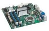
Desktop Board Features Desktop Board Components Figure 1 shows the approximate location of the major components on Desktop Board DG35EC. Figure 1. Desktop Board DG35EC Components 11 - Intel DG35EC | Product Guide - Page 12
LED header High-speed USB 2.0 headers (2) BIOS configuration jumper block Battery S/PDIF connector Front panel audio header Go to the following locations for more information about: • Desktop Board DG35EC • Supported processors http://www.intel.com/design/motherbd http://www.intel.com/go/findCPU - Intel DG35EC | Product Guide - Page 13
connects to the Desktop Board through the LGA775 socket. Go to the following locations for more information about: • Instructions on installing or upgrading the processor, page 29 in Chapter 2 • Supported processors for Desktop Board DG35EC, http://www.intel.com/go/findCPU Main Memory NOTE To be - Intel DG35EC | Product Guide - Page 14
Desktop Board DG35EC Product Guide Go to the following locations for more information about: • SDRAM specifications, http://www.intel.com/technology/memory/ • Installing memory, page 34 in Chapter 2 • Tested memory, http://www.cmtlabs.com/mbsearch.asp or http://www.intel.com/products/motherboard - Intel DG35EC | Product Guide - Page 15
High Definition front panel audio header) • All back panel audio connectors support automatic re-tasking Go to the following locations for more information about: • Audio drivers and utilities http://support.intel.com/support/motherboards/desktop/ • The front panel audio solution, page 45 • The - Intel DG35EC | Product Guide - Page 16
Intel Desktop Board DG35EC Product Guide Legacy Input/Output (I/O) Controller The I/O controller features the following: • Low pin count (LPC) interface • One serial port interface via an onboard header • One diskette drive interface • Serial IRQ interface compatible with serialized IRQ support for - Intel DG35EC | Product Guide - Page 17
LAN activity is occurring 10 Mb/s data rate 100 Mb/s data rate 1000 Mb/s data rate Hi-Speed USB 2.0 Support The Desktop Board supports up to 10 USB 2.0 ports (six ports routed to the back panel and four ports routed to two internal headers) via ICH8. USB 2.0 ports are backward compatible with USB - Intel DG35EC | Product Guide - Page 18
Intel Desktop Board DG35EC Product Guide Expandability For system expansion, the Desktop Board provides the following expansion slots: • One PCI Express x16 connector • Two PCI Express x1 connectors • One PCI bus connector BIOS The BIOS provides the Power-On Self-Test (POST), the BIOS Setup program, - Intel DG35EC | Product Guide - Page 19
instructions on resetting the password, see Clearing Passwords on page 52. Hardware Management Features The hardware management features of Desktop Board DG35EC enable the board to be compatible with the Wired for Management (WfM) specification. The board in the processor, GMCH, The board supports a - Intel DG35EC | Product Guide - Page 20
Intel Desktop Board DG35EC Product Guide Power Management Features Power management is implemented at several levels, including: • Software support through the Advanced Configuration and Power Interface (ACPI) • Hardware support: ⎯ Power connectors ⎯ Fan headers ⎯ LAN wake capabilities ⎯ Instantly - Intel DG35EC | Product Guide - Page 21
sleep state) configuration. If the standby current necessary to support multiple wake events from the PCI and/or USB buses exceeds power supply capacity, the Desktop Board may lose register settings stored in memory. Instantly Available PC technology enables the board to enter the ACPI S3 (Suspend - Intel DG35EC | Product Guide - Page 22
at the memory module sockets and the PCI bus connectors. Figure 3. Location of the +5 V Standby Power Indicator For more information on standby current requirements for the Desktop Board, refer to the Technical Product Specification by going to http://support.intel.com/support/motherboards/desktop - Intel DG35EC | Product Guide - Page 23
STAR requirements. For information about the ENERGY STAR specifications, see: http://www3.intel.com/cd/channel/reseller/asmo-na/eng/337748.htm. Speaker A speaker is mounted on the Desktop Board. The speaker provides audible error code (beep code) information during the Power-On Self-Test (POST - Intel DG35EC | Product Guide - Page 24
Intel Desktop Board DG35EC Product Guide 24 - Intel DG35EC | Product Guide - Page 25
shield • Install and remove the Desktop Board • Install and remove a processor • Install and remove memory • Install and remove a PCI Express x16 card • Connect the diskette drive cable • Connect the IDE and Serial ATA cables • Connect to the internal headers • Connect to the onboard audio system - Intel DG35EC | Product Guide - Page 26
Intel Desktop Board DG35EC Product Guide Installation Precautions When you install and test the Intel Desktop Board, observe all warnings and cautions in the installation instructions. To avoid injury, be careful of: • Sharp pins on connectors • Sharp pins on printed circuit assemblies • Rough edges - Intel DG35EC | Product Guide - Page 27
components from dust and foreign objects, and promotes correct airflow within the chassis. Install the I/O shield before installing the Desktop Board in the chassis. Place the shield inside the chassis as shown in Figure 4. Press the shield into place so that it fits tightly and securely. If the - Intel DG35EC | Product Guide - Page 28
Intel Desktop Board DG35EC Product Guide Installing and Removing the Desktop Board CAUTION Only qualified technical manual for instructions on installing and removing the Desktop Board. Figure 5 shows the location of the mounting screw holes for Desktop Board DG35EC. Figure 5. Desktop Board DG35EC - Intel DG35EC | Product Guide - Page 29
Installing and Replacing Desktop Board Components Installing and Removing a Processor Instructions on how to install the processor to the Desktop Board are given below. Installing a Processor CAUTION Before installing or removing the processor, make sure the AC power has been removed by unplugging - Intel DG35EC | Product Guide - Page 30
Intel Desktop Board DG35EC Product Guide 3. Lift the load plate (Figure 7, A). Do not touch the socket contacts (Figure 7, B). Figure 7. Lift the Load Plate 4. Remove the plastic protective socket cover from the load plate (Figure 8). Do not discard the protective socket cover. Always replace the - Intel DG35EC | Product Guide - Page 31
and Replacing Desktop Board Components 5. Remove the processor from the protective processor cover. Hold the processor only at the edges, being careful not to touch the bottom of the processor (see Figure 9). Do not discard the protective processor cover. Always replace the processor cover if - Intel DG35EC | Product Guide - Page 32
the socket lever (Figure 11, B). Figure 11. Close the Load Plate Installing a Processor Fan Heat Sink Desktop Board DG35EC has mounting holes for a processor fan heat sink. For instructions on how to attach the processor fan heat sink to the Desktop Board, refer to the boxed processor manual. 32 - Intel DG35EC | Product Guide - Page 33
the onboard fan control, the fan will always operate at full speed. Figure 12. Connecting the Processor Fan Heat Sink Cable to the Processor Fan Header Removing the Processor For instructions on how to remove the processor fan heat sink and processor, refer to the processor installation manual. 33 - Intel DG35EC | Product Guide - Page 34
Intel Desktop Board DG35EC Product Guide Installing and Removing Memory NOTE To be fully compliant with all applicable Intel SDRAM memory specifications, the board requires DIMMs that support the Serial Presence Detect (SPD) data structure. Desktop board DG35EC has four 240-pin DDR2 DIMM sockets - Intel DG35EC | Product Guide - Page 35
Installing and Replacing Desktop Board Components If additional memory is to be used, install another matched pair of DIMMs in DIMM 1 (black) in channels A and B (see Figure 14). Figure 14. Dual Channel Memory Configuration with Four DIMMs Three DIMMs If you want to use three DIMMs in a dual-channel - Intel DG35EC | Product Guide - Page 36
Intel Desktop Board DG35EC Product Guide Installing DIMMs To make sure you have the correct DIMM, place it on the illustration of the DDR2 DIMM in Figure 16. All the notches should match with the DDR2 DIMM. Figure 16. Use DDR2 DIMMs 36 - Intel DG35EC | Product Guide - Page 37
Installing and Replacing Desktop Board Components To install a DIMM, follow these steps: 1. Observe Remove the computer's cover and locate the DIMM sockets (see Figure 17). Figure 17. Installing a DIMM 4. Make sure the clips at either end of the DIMM socket(s) are pushed outward to the open position. - Intel DG35EC | Product Guide - Page 38
Intel Desktop Board DG35EC Product Guide Removing DIMMs To remove a DIMM, follow these steps: 1. Observe spread the retaining clips at each end of the DIMM socket. The DIMM pops out of the socket. 6. Hold the DIMM by the edges, lift it away from the socket, and store it in an anti-static package. 7. - Intel DG35EC | Product Guide - Page 39
connector, an electrical short may result across the PCI Express connector pins. Depending on the over-current protection of the power supply, certain Desktop Board components and/or traces may be damaged. Installing a PCI Express x16 Card 1. Observe the precautions in "Before You Begin" on page 25 - Intel DG35EC | Product Guide - Page 40
Intel Desktop Board DG35EC Product Guide Removing the PCI Express x16 Card Follow these instructions to remove the PCI Express x16 card from the connector: 1. Observe the precautions in "Before You Begin" on page 25. 2. Remove the screw (Figure 19, A) - Intel DG35EC | Product Guide - Page 41
cable: • Observe the precautions in "Before You Begin" on page 25. • Attach the cable end labeled P1 to the diskette drive connector on the Intel Desktop Board (Figure 20, A). • Attach the cable end labeled P2 to the diskette drive (Figure 20, B). Figure 20. Connecting the Diskette Drive Cable 41 - Intel DG35EC | Product Guide - Page 42
Intel Desktop Board DG35EC Product Guide Connecting the IDE Cable The IDE cable can be used to connect two IDE drives to the Desktop Board. The cable supports the ATA-66/100 transfer protocol. Figure 21 shows the correct installation of the cable. NOTES ATA-66/100 compatible cables are backward - Intel DG35EC | Product Guide - Page 43
Components Connecting Serial ATA (SATA) Cables SATA cables support the Serial ATA protocol. Each cable can be used to connect a single SATA drive to the Desktop Board. For correct cable function: 1. Observe the precautions in "Before You Begin" on page 25. 2. Attach one end the SATA cable to one - Intel DG35EC | Product Guide - Page 44
Intel Desktop Board DG35EC Product Guide Connecting to the Internal Headers and Connectors Before Description A S/PDIF B Front panel audio C IEEE 1394a D Serial port Item Description E Front panel F Alternate front panel power LED G USB 2.0 H Chassis intrusion Figure 23. - Intel DG35EC | Product Guide - Page 45
Installing and Replacing Desktop Board Components S/PDIF Connector Figure 23, A shows the location the front panel audio header. Table 5 shows the pin assignments for the front panel audio header. Table 5. Front Panel Audio Header Signal Names for Intel® High Definition Audio Pin Signal Name - Intel DG35EC | Product Guide - Page 46
Intel Desktop Board DG35EC Product Guide IEEE 1394a Header See Figure 23, C for the Front panel green LED 3 Hard disk active LED Out 4 Front panel yellow LED Reset Switch On/Off Switch 5 Ground 6 Power switch 7 Reset switch In 8 Ground Power Not Connected 9 Power Out 10 No pin In/ - Intel DG35EC | Product Guide - Page 47
Installing and Replacing Desktop Board Components Alternate Front Panel Power LED Header Figure 23, unshielded cable attached to a USB port might not meet FCC Class B requirements, even if no device or a low-speed USB device is attached to the cable. Use a shielded cable that meets the requirements - Intel DG35EC | Product Guide - Page 48
Intel Desktop Board DG35EC Product Guide Chassis Intrusion Header Figure 23, H on page 44 Audio System After installing the RealTek audio driver from the Intel Express Installer CD-ROM, the multi-channel audio feature can be enabled. Figure 24 shows the back panel audio connectors. Table 12 lists - Intel DG35EC | Product Guide - Page 49
Installing and Replacing Desktop Board Components Connecting Chassis Fan and Power Supply Cables Chassis Fan Cables Connect chassis fan cables to the 3-pin and 4-pin chassis fan headers on the Desktop Board. Figure 25 shows the location of the chassis fan headers. Figure 25. Location of the Chassis - Intel DG35EC | Product Guide - Page 50
Intel Desktop Board DG35EC Product Guide Power Supply Cables CAUTION Failure to use an appropriate power supply and/or not connecting the 12 V (2 x 2 pin) power connector to the Desktop Board may result in damage to the board or the system may not function properly. The 2 x 12 pin main power - Intel DG35EC | Product Guide - Page 51
operation. Figure 27 shows the location of the Desktop Board's BIOS configuration jumper block. Figure 27. Location of the BIOS Configuration Jumper Block The three-pin BIOS jumper block enables all board configurations to be done in the BIOS Setup program. Table 13 shows the jumper settings - Intel DG35EC | Product Guide - Page 52
Intel Desktop Board DG35EC Product Guide Table 13. Jumper Settings for the BIOS Setup Program Modes Jumper Setting Mode Normal (default) (1-2) Description The BIOS uses the current configuration and passwords for booting. Configure (2-3) Recovery (None) After the Power-On Self-Test (POST) runs, - Intel DG35EC | Product Guide - Page 53
and Replacing Desktop Board Components 12. To restore normal operation, place the jumper on pins 1-2 as shown below. 13. Replace the cover, plug in the computer, and turn on the computer. Replacing the Battery A coin-cell battery (CR2032) powers the real-time clock and CMOS memory. When the - Intel DG35EC | Product Guide - Page 54
Intel Desktop Board DG35EC Product Guide VARO Räjähdysvaara, jos pariston tyyppi on väärä. Paristot on kierrätettävä, jos se on mahdollista. Käytetyt paristot on hävitettävä paikallisten ympäristömääräysten mukaisesti. VORSICHT Bei - Intel DG35EC | Product Guide - Page 55
Installing and Replacing Desktop Board Components VIGYÁZAT Ha a telepet nem a megfelelő típusú telepre cseréli, az felrobbanhat. A telepeket lehetőség szerint újra kell hasznosítani. A használt telepeket a helyi környezetvé - Intel DG35EC | Product Guide - Page 56
Intel Desktop Board DG35EC Product Guide POZOR Zamenjava baterije z baterijo drugačnega tipa lahko povzroči eksplozijo. Če je mogoče, baterije reciklirajte. Rabljene baterije zavrzite v skladu z lokalnimi okoljevarstvenimi predpisi. . UYARI Yanlış türde pil - Intel DG35EC | Product Guide - Page 57
Installing and Replacing Desktop Board Components To replace the battery, follow these steps: 1. the computer cover. 4. Locate the battery on the board (see Figure 28). 5. With a medium flat-bladed screwdriver, gently pry the battery free from its connector. Note the orientation of the "+" and - Intel DG35EC | Product Guide - Page 58
Intel Desktop Board DG35EC Product Guide 58 - Intel DG35EC | Product Guide - Page 59
. To update the BIOS with the Intel Express BIOS Update utility: 1. Go to the Intel World Wide Web site: http://support.intel.com/support/motherboards/desktop/ 2. Navigate to the DG35EC page, click "[view] Latest BIOS updates," and select the Express BIOS Update utility file. 3. Download the file to - Intel DG35EC | Product Guide - Page 60
Intel® Integrator Toolkit Configuration File (optional) • Intel Flash Memory Update Utility You can obtain either of these files through your computer supplier or by navigating to the Desktop Board DG35EC page on the Intel World Wide Web site at http://support.intel.com/support/motherboards/desktop - Intel DG35EC | Product Guide - Page 61
Intel Desktop Board BIOS Upgrade CD-ROM" page, press any key to confirm the BIOS upgrade operation. 6. Wait for the BIOS upgrade process to complete. CAUTION DO NOT POWER DOWN YOUR COMPUTER before the update is complete. The update may take up to 5 minutes. Updating the BIOS with the Iflash Memory - Intel DG35EC | Product Guide - Page 62
Intel Desktop Board DG35EC Product Guide CAUTION Do not interrupt the process or the system may not function properly. 1. Uncompress the BIOS update file and copy the .BIO file, IFLASH.EXE, and .ITK file (optional) to a bootable USB flash drive or other bootable USB media. 2. Configure the BIOS or - Intel DG35EC | Product Guide - Page 63
checksum to zero. Table 14 lists the BIOS codes. Table 14. Beep Codes Beep 3 Siren Description No memory Processor overheat (on reboot) BIOS Error Messages When a recoverable error occurs during the POST, the BIOS displays an error message describing the problem. Table 15 gives an explanation - Intel DG35EC | Product Guide - Page 64
Intel Desktop Board DG35EC Product Guide 64 - Intel DG35EC | Product Guide - Page 65
Ecology statements • Electromagnetic Compatibility (EMC) regulations • Product certifications Safety Standards Desktop Board DG35EC complies with the safety Battery Marking There is insufficient space on this Desktop Board to provide instructions for replacing and disposing of the Lithium ion coin - Intel DG35EC | Product Guide - Page 66
Intel Desktop Board DG35EC Product Guide European Union Declaration of Conformity Statement We, Intel Corporation, declare under our sole responsibility that the product Intel® Desktop Board DG35EC is in conformity with all applicable essential requirements necessary for CE marking, following the - Intel DG35EC | Product Guide - Page 67
consult http://www.intel.com/intel/other/ehs/product_ecology for the details of this program, including the scope of covered products, available locations, shipping instructions, terms and conditions, etc Intel Product Recycling Program http://www.intel.com/intel/other/ehs/product_ecology 67 - Intel DG35EC | Product Guide - Page 68
Intel Desktop Board DG35EC Product Guide Deutsch Als Teil von Intels Engagement für den Umweltschutz hat das Unternehmen das Intel Produkt-Recyclingprogramm implementiert, das Einzelhandelskunden von Intel , les instructions d'expédition, les conditions générales, etc. http://www.intel.com/in - Intel DG35EC | Product Guide - Page 69
produtos cobertos, os locais disponíveis, as instruções de envio, os termos e condições, etc. Russian Intel Intel (Product Recycling Program Intel http://www.intel.com/intel/other/ehs/product_ecology Türkçe Intel, çevre sorumluluğuna bağımlılığının bir parçası olarak, perakende tüketicilerin - Intel DG35EC | Product Guide - Page 70
Intel Desktop Board DG35EC Product Guide Lead-free 2LI/Pb-free 2LI Board The electronics industry is transitioning to European Union (EU) Restriction of Hazardous Substances (RoHS)-compliant products. The RoHS legislation restricts the use of six materials. - Intel DG35EC | Product Guide - Page 71
(PBDE) The maximum concentrations allowed are 0.1% or 1000 ppm (except for cadmium, which is limited to 0.01% or 100 ppm) by weight of homogeneous material. Desktop Board DG35EC complies with these restrictions. 71 - Intel DG35EC | Product Guide - Page 72
is defined as the number of years for which listed controlled substances will not leak or chemically deteriorate while in the product. The EFUP for Intel Desktop Boards has been determined to be 10 years. The EFUP for Desktop Board DG35EC is shown in Table 18. Table 18. China RoHS Environmentally - Intel DG35EC | Product Guide - Page 73
Regulatory Compliance The China MII stipulates that a material Self Declaration Table (SDT) must be included in a product's user documentation. The SDT for Desktop Board DG35EC is shown in Figure 29. Figure 29. Desktop Board DG35EC China RoHS Material Self Declaration Table 73 - Intel DG35EC | Product Guide - Page 74
Intel Desktop Board DG35EC Product Guide EMC Regulations Desktop Board DG35EC complies with the EMC regulations stated in Table 19 when correctly installed in a compatible host system. Table 19. EMC radio interference. Install and use the equipment according to the instruction manual. 74 - Intel DG35EC | Product Guide - Page 75
environments and other non-residential environments. Ensure Electromagnetic Compatibility (EMC) Compliance Before computer integration, make sure that instructions for the host chassis, power supply, and other modules: • Product certifications or lack of certifications • External I/O cable shielding - Intel DG35EC | Product Guide - Page 76
Guide Product Certifications Board-Level Certification Markings Desktop Board DG35EC has the product certification markings shown in Table 20. Table 20. Product Certification Markings Description UL joint US/Canada Recognized Component mark. Includes adjacent UL file number for Intel Desktop - Intel DG35EC | Product Guide - Page 77
with safety requirements. Wiring and cables must also be UL listed or recognized and suitable for the intended use. The FCC Class B logo with electromagnetic interference (EMI) requirements. In Canada A nationally recognized certification mark such as CSA or cUL signifies compliance with safety - Intel DG35EC | Product Guide - Page 78
Intel Desktop Board DG35EC Product Guide 78
-
 1
1 -
 2
2 -
 3
3 -
 4
4 -
 5
5 -
 6
6 -
 7
7 -
8
-
9
-
10
-
11
-
12
-
13
-
14
-
15
-
16
-
17
-
18
-
19
-
20
-
21
-
22
-
23
-
24
-
25
-
26
-
27
-
28
-
29
-
30
-
31
-
32
-
33
-
34
-
35
-
36
-
37
-
38
-
39
-
40
-
41
-
42
-
43
-
44
-
45
-
46
-
47
-
48
-
49
-
50
-
51
-
52
-
53
-
54
-
55
-
56
-
57
-
58
-
59
-
60
-
61
-
62
-
63
-
64
-
65
-
66
-
67
-
68
-
69
-
70
-
71
-
72
-
73
-
74
-
75
-
76
-
77
-
78
 |
 |

Intel
®
Desktop Board DG35EC
Product Guide
Order Number:
E30452-001