Intel DG35EC Product Guide - Page 46
IEEE 1394a Header, Serial Port Header, Front Panel Header, Table 6. IEEE 1394a Signal Header Names
 |
UPC - 735858200448
View all Intel DG35EC manuals
Add to My Manuals
Save this manual to your list of manuals |
Page 46 highlights
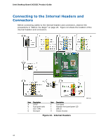
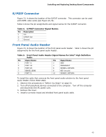
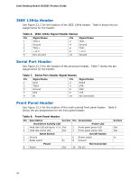
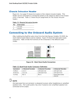
Intel Desktop Board DG35EC Product Guide IEEE 1394a Header See Figure 23, C for the location of the IEEE 1394a header. Table 6 shows the pin assignments for the header. Table 6. IEEE 1394a Signal Header Names Pin Signal Name 1 TPA1+ 3 Ground 5 TPA2+ 7 +12 V 9 Key (no pin) Pin Signal Name 2 TPA1- 4 Ground 6 TPA2- 8 +12 V 10 Ground Serial Port Header See Figure 23, D for the location of the serial port header. Table 7 shows the pin assignments for the header. Table 7. Serial Port Header Signal Names Pin Signal Name 1 DCD 3 TXD# 5 Ground 7 RTS 9 RI Pin Signal Name 2 RXD# 4 DTR 6 DSR 8 CTS 10 No Connection Front Panel Header See Figure 23, E for the location of the multi-colored front panel header. Table 8 shows the pin assignments for the front panel header. Table 8. Front Panel Header Pin Description In/Out Pin Description Hard Drive Activity LED Power LED 1 Hard disk LED pull-up to +5 V Out 2 Front panel green LED 3 Hard disk active LED Out 4 Front panel yellow LED Reset Switch On/Off Switch 5 Ground 6 Power switch 7 Reset switch In 8 Ground Power Not Connected 9 Power Out 10 No pin In/Out Out Out In 46
-
 1
1 -
2
-
3
-
4
-
5
-
6
-
7
-
8
-
9
-
10
-
11
-
12
-
13
-
14
-
15
-
16
-
17
-
18
-
19
-
20
-
21
-
22
-
23
-
24
-
25
-
26
-
27
-
28
-
29
-
30
-
31
-
32
-
33
-
34
-
35
-
36
-
37
-
38
-
39
-
40
-
 41
41 -
 42
42 -
 43
43 -
 44
44 -
 45
45 -
 46
46 -
 47
47 -
 48
48 -
 49
49 -
 50
50 -
 51
51 -
52
-
53
-
54
-
55
-
56
-
57
-
58
-
59
-
60
-
61
-
62
-
63
-
64
-
65
-
66
-
67
-
68
-
69
-
70
-
71
-
72
-
73
-
74
-
75
-
76
-
77
-
78
 |
 |
