Intel DG41CN Product Specification - Page 6

Tables - processors

Page 6 highlights

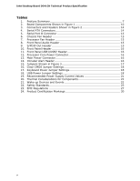
Intel Desktop Board DG41CN Technical Product Specification Tables 1. Feature Summary 7 2. Board Components Shown in Figure 1 10 3. Connectors and Headers Shown in Figure 2 14 4. Serial ATA Connectors 14 5. Serial Port B Connector 15 6. Chassis Fan Header 15 7. Processor Fan Header 15 8. Front Panel Audio Header 15 9. S/PDIF Out Header 15 10. Front Panel Header 16 11. Front Panel USB1/USB2 Header 16 12. Processor Core Power Connector 16 13. Main Power Connector 16 14. Intruder Alert Header 16 15. Jumpers Shown in Figure 3 17 16. Clear CMOS Jumper Settings 18 17. Keyboard Power Jumper Settings 18 18. USB Power Jumper Settings 18 19. Recommended Power Supply Current Values 21 20. Thermal Considerations for Components 22 21. Wake-up Devices and Events 22 22. Safety Standards 23 23. EMC Regulations 27 24. Product Certification Markings 30 vi

  • 1
  • 2
  • 3
  • 4
  • 5
  • 6
  • 7
  • 8
  • 9
  • 10
  • 11
  • 12
  • 13
  • 14
  • 15
  • 16
  • 17
  • 18
  • 19
  • 20
  • 21
  • 22
  • 23
  • 24
  • 25
  • 26
  • 27
  • 28
  • 29
  • 30
  • 31
  • 32
  • 33
  • 34

Intel Desktop Board DG41CN Technical Product Specification
vi
Tables
1.
Feature Summary
..............................................................................
7
2.
Board Components Shown in Figure 1
................................................
10
3.
Connectors and Headers Shown in Figure 2
.........................................
14
4.
Serial ATA Connectors
......................................................................
14
5.
Serial Port B Connector
....................................................................
15
6.
Chassis Fan Header
.........................................................................
15
7.
Processor Fan Header
......................................................................
15
8.
Front Panel Audio Header
.................................................................
15
9.
S/PDIF Out Header
..........................................................................
15
10. Front Panel Header
..........................................................................
16
11. Front Panel USB1/USB2 Header
.........................................................
16
12. Processor Core Power Connector
........................................................
16
13. Main Power Connector
......................................................................
16
14. Intruder Alert Header
.......................................................................
16
15. Jumpers Shown in Figure 3
...............................................................
17
16. Clear CMOS Jumper Settings
.............................................................
18
17. Keyboard Power Jumper Settings
.......................................................
18
18. USB Power Jumper Settings
..............................................................
18
19. Recommended Power Supply Current Values
.......................................
21
20. Thermal Considerations for Components
.............................................
22
21. Wake-up Devices and Events
............................................................
22
22. Safety Standards
.............................................................................
23
23. EMC Regulations
.............................................................................
27
24. Product Certification Markings
...........................................................
30