Intel DG41TX English Product Guide
Intel DG41TX Manual
 |
View all Intel DG41TX manuals
Add to My Manuals
Save this manual to your list of manuals |
Intel DG41TX manual content summary:
- Intel DG41TX | English Product Guide - Page 1
Intel® Desktop Board DG41TX Product Guide Order Number: E88309-001 - Intel DG41TX | English Product Guide - Page 2
Intel® Desktop Board DG41TX Product Guide Date February 2010 Disclaimer INFORMATION IN THIS DOCUMENT IS PROVIDED IN CONNECTION WITH INTEL sustaining applications. Intel may make changes to specifications and product descriptions at any time, without notice. Intel Desktop Board DG41TX may contain - Intel DG41TX | English Product Guide - Page 3
Installing and Replacing Desktop Board Components: instructions on how to install the Desktop Board and other hardware components 3 Updating the BIOS: instructions on how to update the BIOS A Error Messages and Indicators: information about BIOS error messages and beep codes B Regulatory Compliance - Intel DG41TX | English Product Guide - Page 4
Intel Desktop Board DG41TX Product Guide Terminology The table below gives descriptions of some common terms used in the product guide. Term Description GB Gigabyte (1,073,741,824 bytes) GHz Gigahertz (one billion hertz) KB Kilobyte (1024 bytes) kHz Kilohertz (one thousand hertz) MB - Intel DG41TX | English Product Guide - Page 5
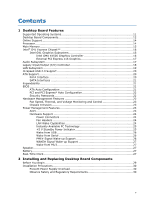
11 Desktop Board Components 12 Online Support 14 Processor ...14 Main Memory...15 Intel® G41 Express Chipset 16 Intel G41 Graphics Subsystem 16 Intel GMA X4500 Graphics Controller 16 External PCI Express x16 Graphics 17 Audio Subsystem 17 Legacy Input/Output (I/O) Controller 18 LAN Subsystem - Intel DG41TX | English Product Guide - Page 6
Image BIOS Update File or the Intel® Flash Memory Update Utility 64 Obtaining the BIOS Update File 64 Updating the BIOS with the ISO Image BIOS Update File 64 Updating the BIOS with the Intel Flash Memory Update Utility 65 Recovering the BIOS 66 A Error Messages and Indicators BIOS Beep Codes - Intel DG41TX | English Product Guide - Page 7
. Internal Headers 47 22. Back Panel Audio Connectors 51 23. Location of the Chassis Fan Headers 52 24. Connecting Power Supply Cables 53 25. Location of the BIOS Configuration Jumper Block 54 26. Removing the Battery 61 27. Intel Desktop Board DG41TX China RoHS Material Self Declaration Table - Intel DG41TX | English Product Guide - Page 8
Intel Desktop Board DG41TX Product Guide Tables 1. Feature Summary 9 2. Intel Desktop Board DG41TX Components 13 3. Back Panel and Front Panel Audio Jack Retasking Support 18 4. LAN Connector LEDs 19 5. Front Panel Audio Header Signal Names for Intel HD Audio 48 6. Front Panel Audio Header - Intel DG41TX | English Product Guide - Page 9
Intel® Desktop Board DG41TX. Table 1 summarizes the major features of the board. Table 1. Feature Summary Form Factor Processor Main Memory Chipset Integrated Graphics External Graphics microATX (243.84 millimeters [9.60 inches] x 243.84 millimeters [9.60 inches]) Support for an Intel® processor - Intel DG41TX | English Product Guide - Page 10
Intel Desktop Board DG41TX Product Guide Table 1. Feature Summary (continued) Peripheral Interfaces BIOS Power Management Hardware Management LAN Support • Eight USB 2.0 ports: ― Four ports routed to the back panel ― Four ports routed to two front panel USB headers • Four Serial ATA (SATA) - Intel DG41TX | English Product Guide - Page 11
Desktop Board Features Supported Operating Systems The Desktop Board supports the following operating systems: • Microsoft Windows* 7 Ultimate • Microsoft Windows 7 Home Premium • Microsoft Windows 7 Basic • Microsoft Windows Vista* Ultimate • Microsoft Windows Vista Enterprise • Microsoft Windows - Intel DG41TX | English Product Guide - Page 12
Intel Desktop Board DG41TX Product Guide Desktop Board Components Figure 1 shows the approximate location of the major components on Intel Desktop Board DG41TX. Figure 1. Intel Desktop Board DG41TX Components 12 - Intel DG41TX | English Product Guide - Page 13
Board Features Table 2. Intel Desktop Board DG41TX Components Label A B C D E F G H I J K L M N O P Q R S T U V W X Y Z AA BB Description Front panel audio header PCI bus connector PCI bus connector PCI Express x1 connector PCI Express x16 connector Speaker Back panel connectors 12 V processor - Intel DG41TX | English Product Guide - Page 14
for Intel Desktop Board DG41TX http://www.intel.com/products/motherboard/DG41TX/in dex.htm • Supported processors http://processormatch.intel.com • Chipset information http://www.intel.com/products/desktop/chipsets/index. htm • BIOS and driver updates http://downloadcenter.intel.com - Intel DG41TX | English Product Guide - Page 15
Desktop Board Features Main Memory NOTE To be fully compliant with all applicable Intel ® SDRAM memory specifications, the board should be populated with DIMMs that support the Serial Presence Detect (SPD) data structure. If your memory modules do not support SPD, you will see a notification to this - Intel DG41TX | English Product Guide - Page 16
Intel Desktop Board DG41TX Product Guide Go to the following locations for more information about: • SDRAM specifications, http://intel.com/technology/memory/ • Installing memory, page 38 in Chapter 2 • Tested memory, http://cmtlabs.com/mbsearch.asp Intel® G41 Express Chipset** The Intel G41 Express - Intel DG41TX | English Product Guide - Page 17
Desktop Board Features • Advanced display support, including: ⎯ DVI specification 1.0 compliant ⎯ Dual independent display support via the DVI-D and VGA back panel connectors ⎯ High Definition Content Protection (HDCP) version 1.1 support ⎯ DDC2B compliant interface with Advanced Digital Display 2 - Intel DG41TX | English Product Guide - Page 18
Intel Desktop Board DG41TX Product Guide Go to the following locations for more information about: • Audio drivers and utilities http://www.intel.com/support/motherboards/desktop • Location of the onboard audio headers, Figure 21 on page 47 • The location and description of the back panel audio - Intel DG41TX | English Product Guide - Page 19
Yellow LED State Off On Blinking Off On On Indicates LAN link is not established LAN link is established LAN activity is occurring 10 Mb/s data rate 100 Mb/s data rate 1000 Mb/s data rate For information about LAN software and drivers go to http://www.intel.com/support/motherboards/desktop 19 - Intel DG41TX | English Product Guide - Page 20
Intel Desktop Board DG41TX Product Guide Hi-Speed USB 2.0 Support The Desktop Board supports up to eight USB 2.0 ports (four ports routed to the back panel 2.0 support requires both an operating system and drivers that fully support USB 2.0 transfer rates. Disabling Hi-Speed USB in the BIOS reverts - Intel DG41TX | English Product Guide - Page 21
the preferred mode for configurations using the Windows* XP and Windows Vista* operating systems. NOTE ACHI is only supported in Microsoft Windows Vista and Microsoft Windows 7 operating systems. Expandability For system expansion, the Desktop Board provides the following expansion slots: • One PCI - Intel DG41TX | English Product Guide - Page 22
. For instructions on resetting the password, see "Clearing Passwords in the BIOS Setup Program" on page 55. Hardware Management Features The hardware management features of Intel Desktop Board DG41TX enable the board to be compatible with the Wired for Management (WfM) specification. The board has - Intel DG41TX | English Product Guide - Page 23
conditions. • Two thermal sensors (processor and a remote thermal sensor). Chassis Intrusion The board supports a chassis security feature that detects if ACPI) • Hardware support: ⎯ Power connectors ⎯ Fan headers ⎯ LAN wake capabilities ⎯ Instantly Available PC technology (Suspend to RAM) ⎯ +5 - Intel DG41TX | English Product Guide - Page 24
Intel Desktop Board DG41TX Product Guide Hardware Support the Last Power State feature in the BIOS Setup program's Boot menu. The Desktop Board has two power connectors. See Figure 24 LAN wakeup capabilities enable remote wake-up of the computer through a network. The LAN subsystem monitors network - Intel DG41TX | English Product Guide - Page 25
front panel, the sleep state is indicated by the LED turning amber. When signaled by a wake-up device or event, the computer quickly returns to its last known awake state. The Desktop Board supports the PCI Bus Power Management Interface Specification. Add-in cards that support this specification - Intel DG41TX | English Product Guide - Page 26
Intel Desktop Board DG41TX Product Guide Figure 3. Location of the +5 V Standby Power Indicator For more information on standby current requirements for the Desktop Board, refer to the Technical Product Specification at http://www.intel.com/support/motherboards/desktop. Wake from USB NOTE Wake from - Intel DG41TX | English Product Guide - Page 27
is mounted on the Desktop Board. The speaker provides audible error code (beep code) information during the Power-On Self-Test (POST). Battery A battery on the Desktop Board keeps the values in CMOS RAM and the clock current when the computer is turned off. Go to page 56 for instructions on how to - Intel DG41TX | English Product Guide - Page 28
Intel Desktop Board DG41TX Product Guide 28 - Intel DG41TX | English Product Guide - Page 29
remove the Desktop Board • Install and remove a processor • Install and remove memory • Install networks, or modems before you open the computer or perform any procedures can result in personal injury or equipment damage. Some circuitry on the board can continue to operate even though the front panel - Intel DG41TX | English Product Guide - Page 30
Intel Desktop Board DG41TX Product Guide Installation Precautions When you install and test the Desktop Board, observe all warnings and cautions in the installation instructions. To avoid injury, be careful of: • Sharp pins on connectors • Sharp pins on printed circuit assemblies • Rough edges and - Intel DG41TX | English Product Guide - Page 31
transmissions, protects internal components from dust and foreign objects, and promotes correct airflow within the chassis. Install the I/O shield before installing the Desktop Board in the chassis. Place the shield inside the chassis as shown in Figure 4. Press the shield into place so that it fits - Intel DG41TX | English Product Guide - Page 32
Intel Desktop Board DG41TX Product Guide Installing and Removing the Desktop Board CAUTION Only qualified manual for instructions on installing and removing the Desktop Board. Figure 5 shows the location of the mounting screw holes for Intel Desktop Board DG41TX. Figure 5. Intel Desktop Board DG41TX - Intel DG41TX | English Product Guide - Page 33
and remove a processor on the Desktop Board. Installing a Processor CAUTION Before installing or removing the processor, make sure page 26). Failure to do so could damage the processor and the board. To install a processor, follow these instructions: 1. Observe the precautions in "Before You Begin" - Intel DG41TX | English Product Guide - Page 34
Intel Desktop Board DG41TX Product Guide 3. Lift the load plate (Figure 7, A). Do not touch the socket contacts (Figure 7, B). Figure 7. Lift the Load Plate 4. Remove the plastic protective socket cover from the - Intel DG41TX | English Product Guide - Page 35
and Replacing Desktop Board Components 5. Remove the processor from the protective processor cover. Hold the processor only at the edges, being careful not to touch the bottom of the processor (see Figure 9). Do not discard the protective processor cover. Always replace the processor cover if - Intel DG41TX | English Product Guide - Page 36
Close the Load Plate Installing a Processor Fan Heat Sink Intel Desktop Board DG41TX has mounting holes for a processor fan heat sink. For instructions on how to attach the processor fan heat sink to the Desktop Board, refer to the boxed processor manual. Connecting the Processor Fan Heat Sink Cable - Intel DG41TX | English Product Guide - Page 37
Installing and Replacing Desktop Board Components Figure 12. Connecting the Processor Fan Heat Sink Cable Removing the Processor For instructions on how to remove the processor fan heat sink and processor, refer to the processor installation manual. 37 - Intel DG41TX | English Product Guide - Page 38
Intel Desktop Board DG41TX Product Guide Installing and Removing Memory The Desktop Board has two 240-pin DDR3 DIMM sockets providing Channel A and Channel B. For optimum dual-channel performance, install a matched pair of DIMMs equal in speed and size (see Figure 13). Figure 13. Dual-Channel Memory - Intel DG41TX | English Product Guide - Page 39
Installing and Replacing Desktop Board Components Installing DIMMs To make sure you have the correct DIMM, place it on the illustration of the DDR3 DIMM in Figure 14. All the notches should match with the DDR3 DIMM. Figure 14. Use DDR3 DIMMs 39 - Intel DG41TX | English Product Guide - Page 40
Intel Desktop Board DG41TX Product Guide To install a DIMM, follow these steps: 1. Observe the precautions in "Before You Begin" on page 29. 2. Turn off all peripheral devices connected to the computer. - Intel DG41TX | English Product Guide - Page 41
Installing and Replacing Desktop Board Components Removing DIMMs To remove a DIMM, follow these steps: 1. Observe the precautions in "Before You Begin" on page 29. 2. Turn off all peripheral devices connected - Intel DG41TX | English Product Guide - Page 42
Intel Desktop Board DG41TX Product Guide Installing and Removing a PCI Express x16 Card CAUTION When installing a PCI Express x16 card on the Desktop Board, ensure that the card is 's metal bracket to the chassis back panel with a screw (Figure 16, B). Figure 16. Installing a PCI Express x16 Card 42 - Intel DG41TX | English Product Guide - Page 43
Desktop Board Components Removing the PCI Express x16 Card Follow these instructions to remove the PCI Express x16 card from the connector: 1. Observe the precautions in "Before You Begin" on page 29. 2. Remove the screw (Figure 17, A) that secures the card's metal bracket to the chassis back panel - Intel DG41TX | English Product Guide - Page 44
Intel Desktop Board DG41TX Product Guide Connecting a PATA (IDE) Cable An IDE cable can be used to connect two IDE drives to the Desktop Board. The cable supports the ATA-66/100 transfer protocol. Figure 18 shows the correct installation of the cable. NOTES ATA-66/100 compatible cables are backward - Intel DG41TX | English Product Guide - Page 45
Components Connecting Serial ATA (SATA) Cables SATA cables support the Serial ATA (SATA) protocol. Each cable can be used to connect a single SATA drive to the Desktop Board. For correct cable function: 1. Observe the precautions in "Before You Begin" on page 29. 2. Attach one end the SATA cable - Intel DG41TX | English Product Guide - Page 46
Intel Desktop Board DG41TX Product Guide Connecting the Diskette Drive Cable A diskette drive cable can be used to connect a single diskette drive to the Desktop Board. For correct function of the cable: 1. Observe the precautions in "Before You Begin" on page 29. 2. Attach the cable end labeled P1 - Intel DG41TX | English Product Guide - Page 47
Installing and Replacing Desktop Board Components Connecting to Internal Headers Before connecting cables to the internal headers, observe the precautions in "Before You Begin" on page 29. Figure 21 shows the location of the internal headers. Figure 21. Internal Headers 47 - Intel DG41TX | English Product Guide - Page 48
Intel Desktop Board DG41TX Product Guide Front Panel HD Audio Header The front panel audio header shown in Figure 21, A supports both Intel HD Audio and AC '97 Audio. Table 5 shows the pin assignments and signal names for HD Audio and Table 6 shows the pin assignments and signal - Intel DG41TX | English Product Guide - Page 49
Installing and Replacing Desktop Board Components Serial Port Header See Figure 21, C for the location of the serial port header. Table 8 shows the pin assignments for the header. Table 8. Serial - Intel DG41TX | English Product Guide - Page 50
Intel Desktop Board DG41TX Product Guide Chassis Intrusion Header Figure 21, E shows the V Out 3 Hard disk active LED Out Reset Switch 5 Ground 7 Reset switch In 2 Front panel green LED 4 Front panel yellow LED On/Off Switch 6 Power switch 8 Ground Power Not Connected 9 Power Out 10 - Intel DG41TX | English Product Guide - Page 51
Installing and Replacing Desktop Board Components S/PDIF Header Figure 21, H shows the location of the the audio driver, the multi-channel audio feature can be enabled. Figure 22 shows the back panel audio connectors. Item Description A Line in/rear surround B Line out/front speakers/headphones - Intel DG41TX | English Product Guide - Page 52
Intel Desktop Board DG41TX Product Guide Connecting Chassis Fan and Power Supply Cables Chassis Fan Cables Connect chassis fan cables to the chassis fan headers on the Desktop Board. Figure 23 shows the location of the chassis fan headers. Figure 23. Location of the Chassis Fan Headers 52 - Intel DG41TX | English Product Guide - Page 53
and/or not connecting the 12 V (2 x 2 pin) power connector to the Desktop Board may result in damage to the board or the system may not function properly. The 2 x 12 pin main power connector on the Desktop Board is backwards compatible with ATX12V power supplies with 2 x 10 connectors. Figure 24 - Intel DG41TX | English Product Guide - Page 54
Intel Desktop Board DG41TX Product Guide Setting the BIOS Configuration Jumper NOTE Always turn off the power and unplug the power cord from the computer before moving the jumper. Moving the jumper with the - Intel DG41TX | English Product Guide - Page 55
the Maintenance Menu. Use this menu to clear passwords. Recovery (None) The BIOS recovers data in the event of a failed BIOS update. Clearing Passwords in the BIOS Setup Program This procedure assumes that the board is installed in the computer and the configuration jumper block is set to normal - Intel DG41TX | English Product Guide - Page 56
Intel Desktop Board DG41TX Product Guide -cell battery (CR2032) powers the real-time clock and CMOS memory. When the computer is not plugged into a wall socket, the the voltage drops below a certain level, the BIOS Setup program settings stored in CMOS RAM (for example, the date and time) might not - Intel DG41TX | English Product Guide - Page 57
Installing and Replacing Desktop Board Components VIKTIGT! Risk för explosion om batteriet ersätts med felaktig batterityp. Batterier ska kasseras enligt de lokala miljövårdsbestämmelserna. VARO Räjähdysvaara, jos pariston tyyppi - Intel DG41TX | English Product Guide - Page 58
Intel Desktop Board DG41TX Product Guide UPOZORNÌNÍ V případě výměny baterie za nesprávný druh může dojít k výbuchu. Je-li to možné, baterie by měly být recyklovány. Baterie je třeba zlikvidovat v souladu s místní - Intel DG41TX | English Product Guide - Page 59
Installing and Replacing Desktop Board Components UPOZORNENIE Ak batériu vymeníte za nesprávny typ, hrozí nebezpečenstvo jej výbuchu. Batérie by sa mali podľa možnosti vždy - Intel DG41TX | English Product Guide - Page 60
Intel Desktop Board DG41TX Product Guide 60 - Intel DG41TX | English Product Guide - Page 61
Installing and Replacing Desktop Board Components To replace the battery, follow these steps: 1. source (wall outlet or power adapter). 3. Remove the computer cover. 4. Locate the battery on the board (see Figure 26). 5. Gently lift the battery retention clip away from the battery holder as shown - Intel DG41TX | English Product Guide - Page 62
Intel Desktop Board DG41TX Product Guide 62 - Intel DG41TX | English Product Guide - Page 63
of the Intel Flash Memory Update Utility and the ease of use of Windows-based installation wizards. To update the BIOS with the Intel Express BIOS Update utility: 1. Go to the Intel World Wide Web site: http://www.intel.com/support/motherboards/desktop/DG41TX 2. Navigate to the DG41TX page. Under - Intel DG41TX | English Product Guide - Page 64
://www.intel.com/support/motherboards/desktop. Navigate to the DG41TX page. Under the "Software and drivers" heading, click on "Latest BIOS" to locate the latest BIOS files. Click on the "BIOS Update" link and select the ISO Image BIOS Update file or the Intel Flash Memory BIOS Update file. Updating - Intel DG41TX | English Product Guide - Page 65
flash drive or other bootable USB media. The Intel Flash Memory Update Utility allows you to: • Update the BIOS and Intel Management Engine in flash memory • Update the language section of the BIOS NOTE Review the instructions distributed with the update utility before attempting a BIOS update. 65 - Intel DG41TX | English Product Guide - Page 66
. Due to BIOS size and recovery requirements, a CD-R with the .BIO file in the root directory will be required. NOTE For more information about updating the Intel Desktop Board BIOS or recovering from a BIOS update failure, go to http://support.intel.com/support/motherboards/desktop/sb/CS-022312 - Intel DG41TX | English Product Guide - Page 67
Intel Desktop Board DG41TX reports POST errors in two ways: • By sounding a beep code and blinking the front panel power LED • By displaying an error message on the monitor BIOS Beep Codes Whenever a recoverable error occurs during POST, the BIOS causes the board's speaker to beep and the front - Intel DG41TX | English Product Guide - Page 68
Intel Desktop Board DG41TX Product Guide Table 16. Front-panel Power LED Blink Codes Type F2 Setup/F10 Boot Menu Prompt BIOS update in progress Video error (no addin graphics card installed) Memory error Thermal trip warning Pattern None Note Off when the update begins, then on for 0.5 second, - Intel DG41TX | English Product Guide - Page 69
Battery Caution There is insufficient space on this Desktop Board to provide instructions for replacing and disposing of the Lithium ion coin chassis near the battery. A suitable caution label is included with Intel Desktop Board DG41TX. CAUTION Risk of explosion if the battery is replaced with an - Intel DG41TX | English Product Guide - Page 70
Intel Desktop Board DG41TX Product Guide European Union Declaration of Conformity Statement We, Intel Corporation, declare under our sole responsibility that the product Intel® Desktop Board DG41TX is in conformity with all applicable essential requirements necessary for CE marking, following the - Intel DG41TX | English Product Guide - Page 71
. Please consult http://intel.com/intel/other/ehs/product_ecology for the details of this program, including the scope of covered products, available locations, shipping instructions, terms and conditions, etc Intel Product Recycling Program http://intel.com/intel/other/ehs/product_ecology 71 - Intel DG41TX | English Product Guide - Page 72
Intel Desktop Board DG41TX Product Guide Deutsch Als Teil von Intels Engagement für den Umweltschutz hat das Unternehmen das Intel Produkt-Recyclingprogramm implementiert, das Einzelhandelskunden von Intel , les instructions d'expédition, les conditions générales, etc. http://intel.com/intel/ot her - Intel DG41TX | English Product Guide - Page 73
dos produtos cobertos, os locais disponíveis, as instruções de envio, os termos e condições, etc. Russian Intel Intel (Product Recycling Program Intel http://intel.com/intel/other/ehs/product_ecology Türkçe Intel, çevre sorumluluğuna bağımlılığının bir parçası olarak, perakende tüketicilerin - Intel DG41TX | English Product Guide - Page 74
Intel Desktop Board DG41TX Product Guide China RoHS Intel Desktop Board DG41TX is a China RoHS-compliant product. The China Ministry of Information Industry (MII) stipulates that a material Self Declaration Table (SDT) must be included in a product's user documentation. The SDT for Intel Desktop - Intel DG41TX | English Product Guide - Page 75
Regulatory Compliance EMC Regulations Intel Desktop Board DG41TX complies with the EMC regulations stated in Table 19 radio frequency energy and, if not installed and used in accordance with the instructions, may cause harmful interference to radio communications. However, there is no guarantee - Intel DG41TX | English Product Guide - Page 76
Intel Desktop Board DG41TX Product Guide radio or television reception, which can be determined by turning the equipment off and on, the user is or television receiver in a domestic environment, it may cause radio interference. Install and use the equipment according to the instruction manual. 76 - Intel DG41TX | English Product Guide - Page 77
, as applicable, have passed Class B EMC testing and are marked accordingly. Pay close attention to the following when reading the installation instructions for the host chassis, power supply, and other modules: • Product certifications or lack of certifications • External I/O cable shielding and - Intel DG41TX | English Product Guide - Page 78
Intel Desktop Board DG41TX Product Guide Product Certifications Board-Level Certifications Intel Desktop Board DG41TX has the regulatory compliance marks shown in Table 20. Table 20. Regulatory Compliance Marks Description UL joint US/Canada Recognized Component mark. Includes adjacent UL - Intel DG41TX | English Product Guide - Page 79
safety requirements. The Industry Canada statement at the front of this product guide demonstrates compliance with Canadian EMC regulations. ENERGY STAR*, and recommended configurations, go to http://www.intel.com/go/energystar. The Desktop Board also meets the following international requirements: - Intel DG41TX | English Product Guide - Page 80
Intel Desktop Board DG41TX Product Guide 80
-
 1
1 -
 2
2 -
 3
3 -
 4
4 -
 5
5 -
 6
6 -
 7
7 -
8
-
9
-
10
-
11
-
12
-
13
-
14
-
15
-
16
-
17
-
18
-
19
-
20
-
21
-
22
-
23
-
24
-
25
-
26
-
27
-
28
-
29
-
30
-
31
-
32
-
33
-
34
-
35
-
36
-
37
-
38
-
39
-
40
-
41
-
42
-
43
-
44
-
45
-
46
-
47
-
48
-
49
-
50
-
51
-
52
-
53
-
54
-
55
-
56
-
57
-
58
-
59
-
60
-
61
-
62
-
63
-
64
-
65
-
66
-
67
-
68
-
69
-
70
-
71
-
72
-
73
-
74
-
75
-
76
-
77
-
78
-
79
-
80
 |
 |

Intel
®
Desktop Board DG41TX
Product Guide
Order Number:
E8830
9
-001