Intel DQ67OW DQ67OW Technical Product Specification
Intel DQ67OW Manual
 |
View all Intel DQ67OW manuals
Add to My Manuals
Save this manual to your list of manuals |
Intel DQ67OW manual content summary:
- Intel DQ67OW | DQ67OW Technical Product Specification - Page 1
February 2010 Order Number: G15483-001US The Intel® Desktop Board DQ67OW may contain design defects or errors known as errata that may cause the product to deviate from published specifications. Current characterized errata are documented in the Intel Desktop Board DQ67OW Specification Update. - Intel DQ67OW | DQ67OW Technical Product Specification - Page 2
® Desktop Board DQ67OW Technical Product Specification Date February 2010 This product specification applies to only the standard Intel® Desktop Board DQ67OW with BIOS identifier SWQ6710H.86A. Changes to this specification will be published in the Intel Desktop Board DQ67OW Specification Update - Intel DQ67OW | DQ67OW Technical Product Specification - Page 3
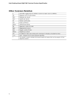
. It is specifically not intended for general audiences. What This Document Contains Chapter 1 2 3 4 5 Description A description of the hardware used on the Intel Desktop Board DQ67OW A map of the resources of the Intel Desktop Board The features supported by the BIOS Setup program A description - Intel DQ67OW | DQ67OW Technical Product Specification - Page 4
Intel Desktop Board DQ67OW Technical Product Specification Other Common Notation # GB GB/s Gb/s KB Kbit kbits/s MB MB/s Mbit Mbits/s xxh x.x V * Used after a signal name to identify an active-low signal (such - Intel DQ67OW | DQ67OW Technical Product Specification - Page 5
1.2 Legacy Considerations 14 1.3 Online Support 14 1.4 Processor 14 1.5 Intel® Q67 Express Chipset 15 1.6 System Memory 15 1.6.1 Memory Configurations 16 1.7 Graphics Subsystem 18 1.7.1 Integrated Graphics 18 1.7.2 PCI Express x16 Graphics 18 1.8 USB 19 1.9 SATA Interfaces 20 1.10 Legacy - Intel DQ67OW | DQ67OW Technical Product Specification - Page 6
Intel Desktop Board DQ67OW Technical Product Specification 2.4 Intel® Management Engine BIOS Extension (Intel® BIOS Features 3.1 Introduction 65 3.2 System Management BIOS (SMBIOS 67 3.3 Legacy USB Support 67 3.4 BIOS Updates 68 3.4.1 Language Support 68 3.4.2 Custom Splash Screen 69 3.5 BIOS - Intel DQ67OW | DQ67OW Technical Product Specification - Page 7
Front Panel Header 53 12. Connection Diagram for Front Panel USB Headers 55 13. Location of the Jumper Block 56 14. Intel MEBX Reset Header 58 15. Board Dimensions 59 16. Localized High Temperature Zones 63 Tables 1. Feature Summary 9 2. Components Shown in Figure 1 12 3. Supported Memory - Intel DQ67OW | DQ67OW Technical Product Specification - Page 8
Intel Desktop Board DQ67OW Technical Product Specification 28. Intel MEBX Reset Header Signals 58 29. Recommended Power Supply Current Values 60 30. Fan Header Current Capability 61 31. Thermal Considerations for Components 63 32. Environmental Specifications 64 33. BIOS Setup Program Menu Bar - Intel DQ67OW | DQ67OW Technical Product Specification - Page 9
• Support for non-ECC memory • Integrated graphics support for processors with Intel® Graphics Technology: ― VGA ― DVI-D • Discrete graphics support for PCI Express 2.0 x16 add-in graphics card • Intel® High Definition Audio: ― Realtek* ALC888S audio codec ― S/PDIF audio header ― Front panel audio - Intel DQ67OW | DQ67OW Technical Product Specification - Page 10
Intel Desktop Board DQ67OW Technical Product Specification Table 1. Feature Summary (continued) Peripheral Interfaces Legacy I/O Control BIOS • Fourteen USB ports: ― Six USB 2.0 ports are implemented with stacked back panel connectors (black) ― Eight USB 2.0 front panel ports are implemented - Intel DQ67OW | DQ67OW Technical Product Specification - Page 11
Product Description 1.1.2 Board Layout Figure 1 shows the location of the major components on Intel Desktop Board DQ67OW. Figure 1. Major Board Components Table 2 lists the components identified in Figure 1. 11 - Intel DQ67OW | DQ67OW Technical Product Specification - Page 12
Intel Desktop Board DQ67OW Technical Product Specification Table 2. Components Shown in Figure 1 Item/callout from Figure 1 Description A Conventional PCI bus add-in card connector B Front panel audio header C PCI Express x4 add-in card connector D Internal mono speaker header E PCI - Intel DQ67OW | DQ67OW Technical Product Specification - Page 13
Product Description 1.1.3 Block Diagram Figure 2 is a block diagram of the major functional areas of the board. Figure 2. Block Diagram 13 - Intel DQ67OW | DQ67OW Technical Product Specification - Page 14
for the Intel Desktop Board DQ67OW Visit this World Wide Web site: http://www.intel.com/products/motherboard/index.htm http://www.intel.com/p/en_US/support?iid=hdr+support http://ark.intel.com Supported processors Chipset information BIOS and driver updates Tested memory Integration information - Intel DQ67OW | DQ67OW Technical Product Specification - Page 15
the processor and the USB, SATA, LPC, audio, network, display, Conventional PCI, and PCI Express. The PCH is a centralized controller for the board's I/O paths. For information about The Intel Q67 Express chipset Resources used by the chipset Refer to http://www.intel.com/products/desktop/chipsets - Intel DQ67OW | DQ67OW Technical Product Specification - Page 16
Intel Desktop Board DQ67OW Technical Product Specification Table 3 lists the supported DIMM configurations. Table 3. Supported Memory Configurations DIMM Capacity Configuration (Note) SDRAM Density SDRAM Organization Front-side/Back-side Number of SDRAM Devices 512 MB SS 1 Gbit 64 M x16/ - Intel DQ67OW | DQ67OW Technical Product Specification - Page 17
Product Description Figure 3 illustrates the memory channel and DIMM configuration. Figure 3. Memory Channel and DIMM Configuration 17 - Intel DQ67OW | DQ67OW Technical Product Specification - Page 18
Intel Desktop Board DQ67OW Technical Product Specification 1.7 Graphics Subsystem The board supports system graphics through either Intel Graphics Technology or a PCI Express 2.0 x16 add-in graphics card. 1.7.1 Integrated Graphics The board supports integrated graphics through the Intel® Flexible - Intel DQ67OW | DQ67OW Technical Product Specification - Page 19
Description 1.8 USB The board supports up to 14 USB 2.0 ports. The Intel Q67 Express Chipset provides the USB controller for the 2.0 ports. The port arrangement is as follows: • Six USB 2.0 ports are implemented with stacked back panel connectors • Eight USB 2.0 front panel ports implemented - Intel DQ67OW | DQ67OW Technical Product Specification - Page 20
Intel Desktop Board DQ67OW Technical Product Specification 1.9 SATA Interfaces The board provides six SATA connectors through the PCH, which support one device per connector: • Two internal SATA 6 Gb/s ports (blue) • Two internal SATA 3 Gb/s ports (black) • Two internal eSATA 3 Gb/s ports for - Intel DQ67OW | DQ67OW Technical Product Specification - Page 21
for the Legacy I/O controller. 1.10.1 Serial Port The serial port is implemented as a 10-pin header on the board. The serial port supports data transfers at speeds up to 115.2 kbits/s with BIOS support. For information about The location of the serial port header Refer to Figure 10, page 45 21 - Intel DQ67OW | DQ67OW Technical Product Specification - Page 22
Intel Desktop Board DQ67OW Technical Product Specification 1.11 Audio Subsystem The board supports Intel High Definition Audio through the Realtek ALC888S audio codec interface. The Realtek ALC888S-based audio subsystem supports the following features: • 8-channel audio with independent multi- - Intel DQ67OW | DQ67OW Technical Product Specification - Page 23
in Figure 4. Back Panel Audio Connector Options The back panel audio connectors are configurable through the audio device drivers. For information about The back panel audio connectors Refer to Section 2.2.1, page 44 The front panel headphone output is supported using a separate audio channel - Intel DQ67OW | DQ67OW Technical Product Specification - Page 24
Intel Desktop Board DQ67OW Technical Product Specification 1.12 LAN Subsystem The LAN subsystem consists of the following: • Intel 82579LM Gigabit Ethernet Controller (10/100/1000 Mbits/s) • RJ-45 LAN connector with integrated status LEDs For information about Obtaining LAN software and drivers - Intel DQ67OW | DQ67OW Technical Product Specification - Page 25
Description Link/Activity LED (green) Link Speed LED (green/yellow) Figure 5. LAN Connector LED Locations Table 4 describes the LED states when the board is powered up and the LAN subsystem is operating. Table 4. LAN Connector LED States LED LED Color LED State Off Link/Activity Green On - Intel DQ67OW | DQ67OW Technical Product Specification - Page 26
Intel Desktop Board DQ67OW Technical Product Specification 1.13 Real-Time Clock Subsystem A coin-cell battery (CR2032) powers the real-time clock and CMOS memory When the voltage drops below a certain level, the BIOS Setup program settings stored in CMOS RAM (for example, the date and time) might not - Intel DQ67OW | DQ67OW Technical Product Specification - Page 27
Product Description 1.14 Thermal Monitoring Figure 6 shows the locations of the thermal sensors and fan headers. Item A B C D Description Thermal diode, located on processor die Processor fan header Front chassis fan header Rear chassis fan header Figure 6. Thermal Sensors and Fan Headers 27 - Intel DQ67OW | DQ67OW Technical Product Specification - Page 28
Intel Desktop Board DQ67OW Technical Product Specification 1.15 Platform Management and Security In addition to Intel AMT the Intel DQ67OW Desktop Board integrates several functions designed to manage the system and lower the total cost of ownership (TCO) of the system. These system management - Intel DQ67OW | DQ67OW Technical Product Specification - Page 29
VT-d) • Intel Fast Call for Help (Intel FCFH) • Trusted Platform Module (TPM) • KVM Remote Control 1.15.3.1 Intel® Active Management Technology (Intel® AMT) Intel Active Management Technology (Intel AMT) offers IT organizations tamperresistant and persistent management capabilities. Specifically - Intel DQ67OW | DQ67OW Technical Product Specification - Page 30
Intel Desktop Board DQ67OW Technical Product Specification • Remote troubleshooting tracking that eliminates time-consuming manual inventory tracking, which also OEM BIOS/Firmware image that provides the Intel Intel AMT-trusted certificate as well as use a remote management application that supports - Intel DQ67OW | DQ67OW Technical Product Specification - Page 31
discontinue the remote access through on-screen pop-up windows. The maximum resolution supported by KVM Remote Control is 1920 x 1200. NOTE KVM Remote Control requires the use of an Intel® processor with integrated graphics. If using simultaneous integrated graphics and add-in PCI Express Graphics - Intel DQ67OW | DQ67OW Technical Product Specification - Page 32
Intel Desktop Board DQ67OW Technical Product Specification 1.15.3.2 Intel® Virtualization Technology (Intel® VT) Intel Virtualization Technology (Intel VT) is a processor technology that enables a platform to run multiple operating systems and applications as independent machines, allowing one - Intel DQ67OW | DQ67OW Technical Product Specification - Page 33
version 1.2 revision 103 component is specifically designed to enhance platform security above support: ⎯ Power connector ⎯ Fan headers ⎯ LAN wake capabilities ⎯ Instantly Available PC technology ⎯ Wake from USB ⎯ Power Management Event signal (PME#) wake-up support ⎯ PCI Express WAKE# signal support - Intel DQ67OW | DQ67OW Technical Product Specification - Page 34
Intel Desktop Board DQ67OW Technical Product Specification 1.16.1 ACPI ACPI gives the operating system direct control over the power management and Plug and Play functions of a computer. The use of ACPI with this board requires an operating system that provides full ACPI support. ACPI features - Intel DQ67OW | DQ67OW Technical Product Specification - Page 35
and user settings to put the system as a whole into a low-power state. Table 6 lists the power states supported by the board along with the associated system power targets. See the ACPI specification for a complete description of the various system and power states. Table 6. Power States and - Intel DQ67OW | DQ67OW Technical Product Specification - Page 36
Desktop Board DQ67OW Technical Product Specification 1.16.1.2 Wake-up Devices and Events Table 7 lists the devices or specific events that can wake the computer from specific states. Table 7. Wake-up Devices and Events These devices/events can wake up the computer... Power switch RTC alarm LAN USB - Intel DQ67OW | DQ67OW Technical Product Specification - Page 37
board provides several power management hardware features, including: • Power connector • Fan headers • LAN wake capabilities • Instantly Available PC technology • Wake from USB • PME# signal wake-up support • WAKE# signal wake-up support Power State feature in the BIOS Setup program's Boot menu. - Intel DQ67OW | DQ67OW Technical Product Specification - Page 38
Intel Desktop Board DQ67OW Technical Product Specification 1.16.2.2 Fan Headers The function/operation of the fan headers is as follows: • The fans are on when the board is in the S0 state • The fans are off when the board Modulation • The front fan and rear fan headers also support linear fan - Intel DQ67OW | DQ67OW Technical Product Specification - Page 39
the front panel power LED will behave as configured by the BIOS "S3 State Indicator" option). When signaled by a wake-up device or event, the system quickly returns to its last known wake state. Table 7 on page 36 lists the devices and events that can wake the computer from the S3 state. The board - Intel DQ67OW | DQ67OW Technical Product Specification - Page 40
Intel Desktop Board DQ67OW Technical Product Specification 1.16.2.10 +5 V Standby Power LED The green +5 V standby power indicator LED shows that power is still present even when the computer appears to be off. Figure 7 shows the location of the Standby Power indicator LED on the board. CAUTION If - Intel DQ67OW | DQ67OW Technical Product Specification - Page 41
2 Technical Reference 2.1 Memory Resources 2.1.1 Addressable Memory The board utilizes 32 GB of addressable system memory. Typically the address space that is allocated for Conventional PCI bus add-in cards, PCI Express configuration space, BIOS (SPI Flash device), and chipset overhead resides above - Intel DQ67OW | DQ67OW Technical Product Specification - Page 42
Intel Desktop Board DQ67OW Technical Product Specification Figure 8. Detailed System Memory Address Map 42 - Intel DQ67OW | DQ67OW Technical Product Specification - Page 43
2.1.2 Memory Map Table 8 lists the system memory map. Table 8. System Memory Map BIOS data (movable by Extended conventionfal mem) ory Conventional memory 2.2 Connectors and Headers CAUTION Only the following connectors and headers have overcurrent protection: back panel and front panel USB - Intel DQ67OW | DQ67OW Technical Product Specification - Page 44
Intel Desktop Board DQ67OW Technical Product Specification 2.2.1 Back Panel Connectors Figure 9 shows the location of the back panel connectors for the board. Item A B C D E F G H I J K Description PS/2 keyboard/mouse connector USB 2.0 ports LAN USB 2.0 ports VGA connector Parallel port DVI-D - Intel DQ67OW | DQ67OW Technical Product Specification - Page 45
Technical Reference 2.2.2 Component-side Connectors and Headers Figure 10 shows the locations of the component-side connectors and headers. Figure 10. Component-side Connectors and Headers Table 9 lists the component-side connectors and headers identified in Figure 10. 45 - Intel DQ67OW | DQ67OW Technical Product Specification - Page 46
Intel Desktop Board DQ67OW Technical Product Specification Table 9. Component-side Connectors and Headers Shown in Figure 10 Item/callout from Figure 10 A B C D E F G H I J K L M N O Description Conventional PCI bus add-in card connector Front panel audio header PCI Express x4 bus add-in card - Intel DQ67OW | DQ67OW Technical Product Specification - Page 47
2 S/PDIF out 3 Key (no pin) 3 +5V_DC Table 12. Internal Mono Speaker Header Pin Signal Name 1 − 2 + Table 13. Front Panel Audio Header for Intel HD Audio Pin Signal Name Pin Signal Name 1 [Port 1] Left channel 3 [Port 1] Right channel 5 [Port 2] Right channel 7 SENSE_SEND - Intel DQ67OW | DQ67OW Technical Product Specification - Page 48
Intel Desktop Board DQ67OW Technical Product Specification Table 14. Front Panel Audio Header for AC '97 Audio Pin Signal Name Pin Signal Name 1 MIC 2 AUD_GND 3 MIC_BIAS 4 AUD_GND 5 FP_OUT_R 6 FP_RETURN_R 7 AUD_5V 8 KEY (no pin) 9 FP_OUT_L 10 FP_RETURN_L - Intel DQ67OW | DQ67OW Technical Product Specification - Page 49
Processor (4-Pin) Fan Header Pin Signal Name 1 Ground 2 +12 V 3 FAN_TACH 4 FAN_CONTROL Table 19. Front and Rear Chassis Fan Headers Pin 4-Wire Support Pin 3-Wire Support 1 Ground 3 Ground 2 +12 V 2 FAN_POWER 3 FAN_TACH 1 FAN_TACH 4 FAN_CONTROL N/A N/A Table 20. Intel - Intel DQ67OW | DQ67OW Technical Product Specification - Page 50
Intel Desktop Board DQ67OW Technical Product Specification Table 21. Diskette Drive Connector Pin Signal Name 1 Ground 2 Density Select 3 Ground 4 Reserved 5 Ground 6 Reserved 7 Ground 8 Index 9 Ground 10 Motor Enable Drive A 11 Ground 12 - Intel DQ67OW | DQ67OW Technical Product Specification - Page 51
capable. • SMBus signals are routed to the Conventional PCI bus connector. This enables Conventional PCI bus add-in boards with SMBus support to access sensor data on the desktop board. The specific SMBus signals are as follows: ⎯ The SMBus clock line is connected to pin A40. ⎯ The SMBus data line - Intel DQ67OW | DQ67OW Technical Product Specification - Page 52
Intel Desktop Board DQ67OW Technical Product Specification 2.2.2.3 Power Supply Connectors The board has the following power supply connectors: • Main power - a 2 x 12 connector. This connector is compatible with 2 x 10 connectors previously used on Intel Desktop boards. The board supports the use - Intel DQ67OW | DQ67OW Technical Product Specification - Page 53
Header This section describes the functions of the front panel header. Table 24 lists the signal names of the front panel header. Figure 11 is a connection diagram for the front panel header. Table 24. Front Panel Header Pin Signal In/ Out Description Hard Drive Activity LED 1 HD_PWR Out - Intel DQ67OW | DQ67OW Technical Product Specification - Page 54
Intel Desktop Board DQ67OW Technical Product Specification 2.2.2.4.2 Reset Switch Header Pins 5 and 7 can be connected to a momentary single pole, single throw (SPST) type switch that is normally open. When the switch is closed, the board resets and runs the POST. 2.2.2.4.3 Power LED Header - Intel DQ67OW | DQ67OW Technical Product Specification - Page 55
Front Panel USB Headers Figure 12 is a connection diagram for the front panel USB headers. NOTE • The +5 V DC power on the USB headers is fused. • Use only a front panel USB connector that conforms to the USB 2.0 specification for high-speed USB devices. Figure 12. Connection Diagram for Front Panel - Intel DQ67OW | DQ67OW Technical Product Specification - Page 56
Intel Desktop Board DQ67OW Technical Product Specification 2.3 BIOS Configuration Jumper Block CAUTION Do not move the jumper with the power on. Always turn off the power and unplug the power cord from the computer before changing a jumper setting. Otherwise, the board could be damaged. Figure 13 - Intel DQ67OW | DQ67OW Technical Product Specification - Page 57
this Configure mode is the only way to clear the BIOS/CMOS settings. Press F9 (restore defaults) while in Configure mode to restore the BIOS/CMOS settings to their default values. Recovery None The BIOS attempts to recover the BIOS configuration. A recovery CD or USB flash drive is required. 57 - Intel DQ67OW | DQ67OW Technical Product Specification - Page 58
Intel Desktop Board DQ67OW Technical Product Specification 2.4 Intel® Management Engine BIOS Extension (Intel® MEBX) Reset Header The Intel® MEBX reset header (see Figure 14) allows you to reset the Intel AMT configuration to the factory defaults. Momentarily shorting pins 1 and 2 with a jumper (not - Intel DQ67OW | DQ67OW Technical Product Specification - Page 59
form factor for the board. Dimensions are given in inches [millimeters]. The outer dimensions are 9.60 inches by 9.60 inches [243.84 millimeters by 243.84 millimeters]. Location of the I/O connectors and mounting holes are in compliance with the ATX specification. Figure 15. Board Dimensions 59 - Intel DQ67OW | DQ67OW Technical Product Specification - Page 60
Intel Desktop Board DQ67OW Technical Product Specification 2.6 Electrical Considerations 2.6.1 Power supported processors), 2 GB DDR3 RAM, one high end video card, one hard disk drive, one optical drive, and all board peripherals enabled, the minimum recommended power supply is 460 W. Table 29 lists - Intel DQ67OW | DQ67OW Technical Product Specification - Page 61
will halt fan operation. Table 30 lists the current capability of the fan headers. Table 30. Fan Header Current Capability Fan Header Maximum Available Current Processor fan Front chassis fan Rear chassis fan 2.0 A 1.5 A 1.5 A 2.6.3 Add-in Board Considerations The board is designed to provide - Intel DQ67OW | DQ67OW Technical Product Specification - Page 62
Intel Desktop Board DQ67OW Technical Product Specification 2.7 Thermal Considerations CAUTION A chassis with a maximum internal ambient temperature of 38 oC at the processor fan inlet is required. Use of a processor Intel makes no warranties or representations that merely following the instructions - Intel DQ67OW | DQ67OW Technical Product Specification - Page 63
important when considering proper airflow to cool the board. Table 31. Thermal Considerations for Components Component Maximum Case Temperature Processor For processor case temperature, see processor datasheets and processor specification updates Intel Q67 Express Chipset 111 oC (under bias - Intel DQ67OW | DQ67OW Technical Product Specification - Page 64
Intel Desktop Board DQ67OW Technical Product Specification 2.8 Reliability The Mean Time Between Failures (MTBF) prediction is calculated using component and subassembly random failure rates. The calculation is based on the Telcordia "Reliability - Intel DQ67OW | DQ67OW Technical Product Specification - Page 65
board uses an Intel BIOS that is stored in a 64 Mbit (8,192 KB) Serial Peripheral Interface Flash Memory (SPI Flash) device which can be updated using a set of utilities. The SPI Flash contains the BIOS Setup program, POST, LAN EEPROM information, Plug and Play support, and other firmware. The BIOS - Intel DQ67OW | DQ67OW Technical Product Specification - Page 66
Intel Desktop Board DQ67OW Technical Product Specification Table 33 lists the BIOS Setup program menu features. Table 33. BIOS Setup Program Menu Bar Maintenance Main Configura- tion Performance Security Power Boot Intel ME Exit Clears passwords and displays processor information Displays - Intel DQ67OW | DQ67OW Technical Product Specification - Page 67
information. Additional board information can be found in the BIOS under the Additional Information header under the Main BIOS page. 3.3 Legacy USB Support Legacy USB support enables USB devices to be used even when the operating system's USB drivers are not yet available. Legacy USB support is used - Intel DQ67OW | DQ67OW Technical Product Specification - Page 68
Intel Desktop Board DQ67OW Technical Product Specification 3.4 BIOS Updates The BIOS can be updated using either of the following utilities, which are available on the Intel World Wide Web site: • Intel® Express BIOS Update utility, which enables automated updating while in the Windows environment. - Intel DQ67OW | DQ67OW Technical Product Specification - Page 69
, for example) Yes USB diskette drive (with a 1.44 MB diskette) No USB hard disk drive No Legacy diskette drive (with a 1.44 MB diskette) connected to the No legacy diskette drive interface For information about BIOS recovery Refer to http://www.intel.com/support/motherboards/desktop/sb/ cs - Intel DQ67OW | DQ67OW Technical Product Specification - Page 70
Intel Desktop Board DQ67OW Technical Product Specification 3.6 Boot Options In the BIOS Setup program, the user can choose to boot drive is supported in compliance to the El Torito bootable CD-ROM format specification. Under the Boot menu in the BIOS Setup program, the optical drive is listed as a - Intel DQ67OW | DQ67OW Technical Product Specification - Page 71
are set in BIOS SETUP and are prompted for during BIOS POST. For convenient support of S3 resume, the system BIOS will automatically unlock manual power cycle will be required to resume system operation. NOTE As implemented on DQ67OW, Hard Disk Drive Password Security is only supported on SATA - Intel DQ67OW | DQ67OW Technical Product Specification - Page 72
Intel Desktop Board DQ67OW Technical Product Specification NOTE Hard Disk Drive Password Security is not supported in PCH RAID mode. Secured hard disk drives attached to the system when the system is in PCH RAID mode will not be accessible due to the disabling of BIOS Hard Disk Drive Password - Intel DQ67OW | DQ67OW Technical Product Specification - Page 73
Overview of BIOS Features Table 38 shows the effects of setting the supervisor password and user password. This table is for reference only and is not displayed on - Intel DQ67OW | DQ67OW Technical Product Specification - Page 74
Intel Desktop Board DQ67OW Technical Product Specification 74 - Intel DQ67OW | DQ67OW Technical Product Specification - Page 75
BIOS Beep Codes Whenever a recoverable error occurs during POST, the BIOS causes the board's piezoelectric speaker to beep an error message describing the problem (see Table 39). Table 39. BIOS 932 Hz 932 Hz For processors requiring an add-in graphics card 932 Hz High beep 2000 Hz Low beep - Intel DQ67OW | DQ67OW Technical Product Specification - Page 76
Intel Desktop Board DQ67OW Technical Product Specification 4.3 Front-panel Power LED Blink Codes Whenever a recoverable error occurs during POST, the BIOS causes the board's front panel power LED to blink an error message describing the problem (see Table 40). Table 40. Front-panel Power LED - Intel DQ67OW | DQ67OW Technical Product Specification - Page 77
-0x20 - S2, 0x30 - S3, etc. Security (SEC) phase PEI phase pre MRC execution MRC memory detection PEI phase post MRC execution Recovery Platform DXE driver CPU Initialization (PEI, DXE, SMM) I/O buses: PCI, USB, ATA etc. 0x5F is an unrecoverable error. Start with PCI. BDS Output devices: All output - Intel DQ67OW | DQ67OW Technical Product Specification - Page 78
Intel Desktop Board DQ67OW Technical Product Specification SEC) Starting BIOS execution after CPU BIST SPI prefetching SATA) LAN init Exit early platform init driver Memory MRC entry point Reading SPD from memory DIMMs Detecting presence of memory DIMMs Configuring memory Testing memory Exit MRC driver - Intel DQ67OW | DQ67OW Technical Product Specification - Page 79
Phase 0x41 Begin CPU PEI Init 0x42 XMM instruction enabling 0x43 End CPU PEI Init CPU PEI SMM Phase 0x44 Begin CPU SMM Init smm relocate bases 0x45 Smm relocate bases for APs 0x46 End CPU SMM Init CPU DXE Phase 0x47 CPU DXE Phase begin 0x48 Refresh memory space attributes according - Intel DQ67OW | DQ67OW Technical Product Specification - Page 80
Intel Desktop Board DQ67OW Technical Product Specification Table 43. Port 80h POST Codes (continued) Port 80 Code Progress Code Enumeration 0x60 0x61 0x62 0x63 0x64 0x65 0x66 0x67 0x68 0x69 0x6A 0x6B 0x6C 0x6D 0x6E 0x6F 0x90 0x91 0x92 0x93 0x94 0x95 0x98 0x99 0x9A 0x9B 0xB0 0xB1 BDS BDS driver - Intel DQ67OW | DQ67OW Technical Product Specification - Page 81
Entered DXE phase BDS 0xE7 Waiting for user input 0xE8 Checking password 0xE9 Entering BIOS setup 0xEB Calling Legacy Option ROMs Runtime Phase/EFI OS Boot 0xF8 EFI boot service ExitBootServices ( ) has been called 0xF9 EFI runtime service SetVirtualAddressMap ( ) has been called 81 - Intel DQ67OW | DQ67OW Technical Product Specification - Page 82
Intel Desktop Board DQ67OW Technical Product Specification Table 44. Typical Port 80h POST Sequence POST Code Description 21 Initializing a chipset component 22 Reading SPD from memory DIMMs 23 Detecting presence of memory DIMMs 25 Configuring memory 28 Testing memory 34 Loading - Intel DQ67OW | DQ67OW Technical Product Specification - Page 83
of Conformity statement • Product Ecology statements • Electromagnetic Compatibility (EMC) standards • Product certification markings 5.1.1 Safety Standards The Intel Desktop Board DQ67OW complies with the safety standards stated in Table 45 when correctly installed in a compatible host system - Intel DQ67OW | DQ67OW Technical Product Specification - Page 84
Intel Desktop Board DQ67OW Technical Product Specification 5.1.2 European Union Declaration of Conformity Statement We, Intel Corporation, declare under our sole responsibility that the product Intel® Desktop Board DQ67OW is in conformity with all applicable essential requirements necessary for - Intel DQ67OW | DQ67OW Technical Product Specification - Page 85
of this program, including the scope of covered products, available locations, shipping instructions, terms and conditions, etc Intel Product Recycling Program http://www.intel.com/intel/other/ehs/product_ecology Deutsch Als Teil von Intels Engagement für den Umweltschutz hat das Unternehmen das - Intel DQ67OW | DQ67OW Technical Product Specification - Page 86
Intel Desktop Board DQ67OW Technical Product Specification Español Como parte de su compromiso de responsabilidad medioambiental, Intel ha implantado el programa de reciclaje de productos Intel, que permite que los consumidores al detalle de los productos Intel devuelvan los productos usados en los - Intel DQ67OW | DQ67OW Technical Product Specification - Page 87
ı, kayıtlar ve şartlar v.s dahil bütün ayrıntılarını ögrenmek için lütfen http://www.intel.com/intel/other/ehs/product_ecology Web sayfasına gidin. 5.1.4 EMC Regulations The Intel Desktop Board DQ67OW complies with the EMC regulations stated in Table 46 when correctly installed in a compatible host - Intel DQ67OW | DQ67OW Technical Product Specification - Page 88
Intel Desktop Board DQ67OW Technical Product Specification FCC Declaration of Conformity This device complies with Part 15 radio frequency energy and, if not installed and used in accordance with the instructions, may cause harmful interference to radio communications. However, there is no guarantee - Intel DQ67OW | DQ67OW Technical Product Specification - Page 89
or television receiver in a domestic environment, it may cause radio interference. Install and use the equipment according to the instruction manual. Korea Class B Statement Korea Class B Statement translation: This equipment is for home use, and has acquired electromagnetic conformity registration - Intel DQ67OW | DQ67OW Technical Product Specification - Page 90
Intel Desktop Board DQ67OW Technical Product Specification 5.1.5 ENERGY STAR* 5.0, e-Standby, and ErP Compliance The US Department of Energy and the US Environmental Protection Agency have continually revised the ENERGY STAR requirements. Intel has worked directly with these two governmental - Intel DQ67OW | DQ67OW Technical Product Specification - Page 91
Regulatory Compliance Marks (Board Level) Intel Desktop Board DQ67OW has the regulatory compliance marks shown in Table 47. Table 47. Regulatory Compliance Marks Description UL joint US/Canada Recognized Component mark. Includes adjacent UL file number for Intel Desktop Boards: E210882. Mark FCC - Intel DQ67OW | DQ67OW Technical Product Specification - Page 92
Intel Desktop Board DQ67OW Technical Product Specification 5.2 Battery Disposal Information CAUTION Risk of explosion if the battery is replaced with an incorrect type. Batteries should be recycled where possible. Disposal of used - Intel DQ67OW | DQ67OW Technical Product Specification - Page 93
Regulatory Compliance and Battery Disposal Information PRECAUCIÓN Existe peligro de explosión si la pila no se cambia de forma adecuada. Utilice solamente pilas iguales o del mismo tipo que las recomendadas por el fabricante del equipo. Para deshacerse de las pilas usadas, siga igualmente las - Intel DQ67OW | DQ67OW Technical Product Specification - Page 94
Intel Desktop Board DQ67OW Technical Product Specification AWAS Risiko letupan wujud jika bateri digantikan dengan jenis yang tidak betul. Bateri sepatutnya dikitar semula jika boleh. Pelupusan bateri terpakai mestilah mematuhi peraturan alam - Intel DQ67OW | DQ67OW Technical Product Specification - Page 95
Regulatory Compliance and Battery Disposal Information 95 - Intel DQ67OW | DQ67OW Technical Product Specification - Page 96
Intel Desktop Board DQ67OW Technical Product Specification 96
-
 1
1 -
 2
2 -
 3
3 -
 4
4 -
 5
5 -
 6
6 -
 7
7 -
8
-
9
-
10
-
11
-
12
-
13
-
14
-
15
-
16
-
17
-
18
-
19
-
20
-
21
-
22
-
23
-
24
-
25
-
26
-
27
-
28
-
29
-
30
-
31
-
32
-
33
-
34
-
35
-
36
-
37
-
38
-
39
-
40
-
41
-
42
-
43
-
44
-
45
-
46
-
47
-
48
-
49
-
50
-
51
-
52
-
53
-
54
-
55
-
56
-
57
-
58
-
59
-
60
-
61
-
62
-
63
-
64
-
65
-
66
-
67
-
68
-
69
-
70
-
71
-
72
-
73
-
74
-
75
-
76
-
77
-
78
-
79
-
80
-
81
-
82
-
83
-
84
-
85
-
86
-
87
-
88
-
89
-
90
-
91
-
92
-
93
-
94
-
95
-
96
 |
 |

Intel® Desktop Board
DQ67OW
Technical Product Specification
February 2010
Order Number:
G15483-001US
The Intel
®
Desktop Board DQ67OW may contain design defects or errors known as errata that may cause the product to deviate from published
specifications.
Current characterized errata are documented in the Intel Desktop Board DQ67OW Specification Update.