Intel DQ963FX Product Guide - Page 42
Intel DQ963FX - Desktop Board Motherboard Manual
 |
UPC - 735858181914
View all Intel DQ963FX manuals
Add to My Manuals
Save this manual to your list of manuals |
Page 42 highlights
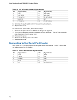
Intel Desktop Board DQ963FX Product Guide Table 6. AC '97 Audio Header Signal Names Pin 1 3 5 7 9 Signal Name MIC MIC_BIAS FP_OUT_R AUD_5V FP_OUT_L Pin 2 4 6 8 10 Signal Name AUD_GND AUD_GND FP_RETURN_R KEY FP_RETURN_L 5. Connect the audio cable to the front panel audio solution. 6. Replace the cover. To restore back panel audio, follow these steps: 1. Observe the precautions in "Before You Begin" on page 25. 2. Turn off all peripheral devices connected to the computer. Turn off the computer and disconnect the AC power cord. 3. Remove the cover. 4. Remove the front panel audio cable. 5. Replace the cover. Connecting to the Serial Port Header See Figure 20, C for the location of the green serial port header. Table 7 shows the pin assignments for the header. Table 7. Serial Port Header Signal Names Pin 1 3 5 7 9 Signal Name DCD TXD# Ground RTS RI Pin 2 4 6 8 10 Signal Name RXD# DTR DSR CTS No Connection 42
-
 1
1 -
2
-
3
-
4
-
5
-
6
-
7
-
8
-
9
-
10
-
11
-
12
-
13
-
14
-
15
-
16
-
17
-
18
-
19
-
20
-
21
-
22
-
23
-
24
-
25
-
26
-
27
-
28
-
29
-
30
-
31
-
32
-
33
-
34
-
35
-
36
-
 37
37 -
 38
38 -
 39
39 -
 40
40 -
 41
41 -
 42
42 -
 43
43 -
 44
44 -
 45
45 -
 46
46 -
 47
47 -
48
-
49
-
50
-
51
-
52
-
53
-
54
-
55
-
56
-
57
-
58
-
59
-
60
-
61
-
62
-
63
-
64
-
65
-
66
-
67
-
68
-
69
-
70
-
71
-
72
 |
 |
