Intel RT3WB080 Hardware User Guide - Page 23
Intel® RAID Controller RT3WB080 Characteristics - battery backup
 |
View all Intel RT3WB080 manuals
Add to My Manuals
Save this manual to your list of manuals |
Page 23 highlights
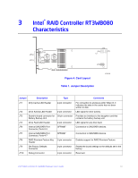
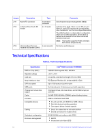
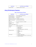
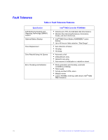
3 Intel® RAID Controller RT3WB080 Characteristics JT12 JT13 JT10 JT7 JT6 JT9 Port 7-4 Port 3-0 JT11 JT8 JT2 JT4 JT1 JT3 Figure 4. Card Layout Table 1. Jumper Description AF003198 Jumper Description Type Comments JT1 Dirty Cache LED Header 2-pin connector For connection to enclosure LED. When lit, it indicates the data in the cache has not been written to disk. JT2 Drive Activity LED Header 2-pin connector LED signal for drive activity. JT3 Board-to-board connector for 20-pin connector Provides an interface to the daughter card that Battery Backup Unit contains the battery backup unit. JT4 Drive Fault LED Header 2-pin connector LED signal for any drive fault. JT6 Internal SAS/SATA Port Connector, Ports 0-3 SFF8087 Connection to SAS/SATA devices. JT7 Internal SAS/SATA Port Connector, Ports 4-7 SFF8087 Connection to SAS/SATA devices. JT8 RAID Premium Feature Key 2-pin connector Enables support for RAID Premium Feature. Header JT9 Set Factory Defaults Connector 2-pin connector Resets the board settings to the defaults set in the factory. JT10 Debug Connector 2-pin connector Reserved. Intel® RAID Controller RT3WB080 Hardware User's Guide 13
-
 1
1 -
2
-
3
-
4
-
5
-
6
-
7
-
8
-
9
-
10
-
11
-
12
-
13
-
14
-
15
-
16
-
17
-
 18
18 -
 19
19 -
 20
20 -
 21
21 -
 22
22 -
 23
23 -
 24
24 -
 25
25 -
 26
26 -
 27
27 -
 28
28 -
29
-
30
-
31
-
32
-
33
-
34
-
35
-
36
-
37
-
38
-
39
-
40
-
41
-
42
-
43
-
44
 |
 |
