Intel S1200BT Technical Product Specification
Intel S1200BT Manual
 |
View all Intel S1200BT manuals
Add to My Manuals
Save this manual to your list of manuals |
Intel S1200BT manual content summary:
- Intel S1200BT | Technical Product Specification - Page 1
Intel® Server Board S1200BT Technical Product Specification Intel order number G13326-004 Revision 2.0 February, 2012 Enterprise Platforms and Services Division - Intel S1200BT | Technical Product Specification - Page 2
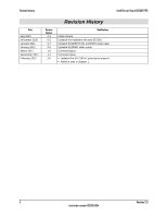
Modifications Initial release. Updated the hardware info and SE SKU. Updated S1200BTS info and BIOS setup page. Updated S1200BT video mode. Corrected typos. Corrected typos. Updated the E3-1200 v2 processors support. Added a note in chapter 1. ii Revision 2.0 Intel order number G13326-004 - Intel S1200BT | Technical Product Specification - Page 3
future changes to them. The Intel® Server Board S1200BT may contain design defects or errors known as errata which may cause the product to deviate from published specifications. Current characterized errata are available on request. Intel Corporation server boards contain a number of high-density - Intel S1200BT | Technical Product Specification - Page 4
Generation Intel® Core™ i3 Processors ...19 3.1.3 Intel® Turbo Boost Technology 19 3.2 Memory Subsystem 20 3.2.1 Memory Supported 20 3.2.2 Post Error Codes 21 3.2.3 Memory Map and Population Rules 22 3.2.4 Publishing System Memory 24 3.2.5 3.3 Memory RAS Support 24 Intel® Chipset PCH - Intel S1200BT | Technical Product Specification - Page 5
...31 3.6.4 Floppy Disk Controller 32 3.6.5 Keyboard and Mouse Support 32 3.6.6 Wake-up Control 32 3.7 3.7.1 3.7.2 Video Support ...32 Intel® Server Board S1200BTL 32 Video for Intel® Server Board S1200BTS 33 3.8 Network Interface Controller (NIC 33 3.8.1 Gigabit Ethernet Controller - Intel S1200BT | Technical Product Specification - Page 6
Capability for Intel® Server Board S1200BTS 49 5.1 Supper I/O...49 5.1.1 Key Features of supper I/O 49 6. BIOS User Interface...50 6.1 BIOS POST Initialization 50 6.1.1 BIOS Revision Identification 50 6.2 HotKeys Supported During POST 51 6.3 POST Logo Screen/Diagnostic Screen 52 - Intel S1200BT | Technical Product Specification - Page 7
8.1.2 Clearing the Password 117 8.2 Integrated BMC Force Update Procedure (Only for The Intel® Server Board S1200BTL) ...118 8.3 ME Force Update Jumper 118 8.4 BIOS Recovery Jumper 119 9. Intel® Light Guided Diagnostics 120 9.1 System Status LED (Only for S1200BTL 120 9.2 Post Code - Intel S1200BT | Technical Product Specification - Page 8
® Server Board S1200BTL 6 Figure 2. Intel® Server Board S1200BTS 7 Figure 3. Intel® Server Board S1200BTL Layout 8 Figure 4. Intel® Server Board S1200BTS Layout 9 Figure 5. Intel® Server Board S1200BTL - Hole and Component Positions 11 Figure 6. Intel® Server Board S1200BTL - Major Connector - Intel S1200BT | Technical Product Specification - Page 9
, J1F2, and J1E2) on S1200BTL 115 Figure 47. Jumper Blocks (J2G1, J1G1, J1H3, and J2J1) on S1200BTS 116 Figure 48. POST Code Diagnostic LED Location 121 Figure 49. Output Voltage Timing 126 Figure 50. Turn On/Off Timing (Power Supply Signals 127 Revision 2.0 ix Intel order number G13326-004 - Intel S1200BT | Technical Product Specification - Page 10
104 Table 27. Front Panel SSI Standard 24-pin Connector Pin-out (J1C1 on S1200BTL or J1C2 on S1200BTS) ...104 Table 28. System Status LED Indicator States 106 Table 29. VGA Connector Pin-out 107 Table 30. RJ-45 10/100/1000 NIC Connector Pin-out 107 x Revision 2.0 Intel order number G13326 - Intel S1200BT | Technical Product Specification - Page 11
41. One PCI X32 connector (J1B1 113 Table 42. SSI 4-pin Fan Header Pin-out 114 Table 43. Server Board Jumpers (J1F1, J1F2, J1F3, J1E2, and J4A2) on S1200BTL............115 Table 44. Server Board Jumpers (J2G1, J1G1, J1H3, and J2J1) on S1200BTS 116 Table 45. Front Panel LED Behavior Summary 120 - Intel S1200BT | Technical Product Specification - Page 12
List of Tables Intel® Server Board S1200BT TPS xii Revision 2.0 Intel order number G13326-004 - Intel S1200BT | Technical Product Specification - Page 13
Integrated BMC Sensor Tables Appendix C - POST Code Diagnostic LED Decoder Appendix D - POST Code Errors Appendix E - Supported Intel® Server Chassis Glossary Reference Documents 1.2 Server Board Use Disclaimer Intel Corporation server boards contain a number of high-density VLSI and power - Intel S1200BT | Technical Product Specification - Page 14
Introduction Intel® Server Board S1200BT TPS blocks to consult vendor datasheets and operating parameters to determine the amount of airflow required for their specific application and environmental conditions. Intel Corporation cannot be held responsible if components fail or the server board - Intel S1200BT | Technical Product Specification - Page 15
has two board SKUs, namely S1200BTL, and S1200BTS. 2.1 Intel® Server Board S1200BT Feature Set Feature Processor Memory Chipset Table 1. Intel® Server Board S1200BT Feature Set Description of S1200BTL Supports for one Intel® Xeon® E31200Processors or the 2nd Generation Intel® Core™ i3 Processors - Intel S1200BT | Technical Product Specification - Page 16
Overview Intel® Server Board S1200BT TPS Feature I/O Add-in PCI Card, PCI Express* Card System Fan Support Video Onboard Hard Drive Description of S1200BTL External connections: DB-15 video connectors DB-9 serial Port A connector Four ports on two USB/LAN combo connectors at rear of board - Intel S1200BT | Technical Product Specification - Page 17
Intel® Server Board S1200BT TPS Overview Feature RAID Support LAN Server Management Security Description of S1200BTL Intel® Embedded Server RAID Technology II through onboard SATA connectors provides SATA RAID 0, 1, and 10 and optional RAID 5 support provided by the Intel® RAID Activation Key - Intel S1200BT | Technical Product Specification - Page 18
Overview 2.2 Server Board Layout Intel® Server Board S1200BT TPS Figure 1. Intel® Server Board S1200BTL 6 Revision 2.0 Intel order number G13326-004 - Intel S1200BT | Technical Product Specification - Page 19
Intel® Server Board S1200BT TPS Overview Figure 2. Intel® Server Board S1200BTS 2.2.1 Server Board Connector and Component Layout The following figure shows the board layout of the server board. Each connector and major component is identified by a number or letter, and Table 2 provides the - Intel S1200BT | Technical Product Specification - Page 20
Intel® Server Board S1200BT TPS Figure 3. Intel® Server Board S1200BTL Layout Table 2. Major Board Components Description A Slot 1, 32 Mbit/33 MHz PCI B TPM C Slot 3/4, PCI Express* Gen2 x4 (x8 connector) D Slot 5, PCI Express* Gen2 x4 (x8 connector) E Slot 6, PCI Express* Gen2 x8 (x16 connector - Intel S1200BT | Technical Product Specification - Page 21
Intel® Server Board S1200BT TPS Description K RMM4 Lite Connector L CPU Power Connector M SYS_FAN_4 N RMM4 Dedicated NIC connector O Four DIMM Slots P P/S AUX Q MAIN POWER Description BB Front Panel Connector CC HDD LED DD Internal USB Connector EE CMOS battery FF Four 3Gb/s SATA ports GG Two 6Gb/s - Intel S1200BT | Technical Product Specification - Page 22
USB COMBO S SYS_FAN_3 G Video port T Six 3Gb/s SATA ports H External Serial port U Low profile USB connector I CPU Power connector V Internal USB J SYS_FAN_2 W CMOS battery K DIMM slots X Front Panel L MAIN power connector Y HDD LED M TPM connector 10 Revision 2.0 Intel order number - Intel S1200BT | Technical Product Specification - Page 23
Intel® Server Board S1200BT TPS 2.2.2 Intel® Server Board S1200BTL Mechanical Drawings Overview Figure 5. Intel® Server Board S1200BTL - Hole and Component Positions Revision 2.0 11 Intel order number G13326-004 - Intel S1200BT | Technical Product Specification - Page 24
Overview Intel® Server Board S1200BT TPS Figure 6. Intel® Server Board S1200BTL - Major Connector Pin Location (1 of 2) 12 Revision 2.0 Intel order number G13326-004 - Intel S1200BT | Technical Product Specification - Page 25
Intel® Server Board S1200BT TPS Overview Figure 7. Intel® Server Board S1200BTL - Major Connector Pin Location (2 of 2) Revision 2.0 13 Intel order number G13326-004 - Intel S1200BT | Technical Product Specification - Page 26
Overview Intel® Server Board S1200BT TPS Figure 8. Intel® Server Board S1200BTL - Primary Side Keepout Zone 14 Revision 2.0 Intel order number G13326-004 - Intel S1200BT | Technical Product Specification - Page 27
Intel® Server Board S1200BT TPS Overview Figure 9. Intel® Server Board S1200BTL - Secondary Side Keepout Zone Revision 2.0 15 Intel order number G13326-004 - Intel S1200BT | Technical Product Specification - Page 28
figure shows the layout of the rear I/O components for the server board. A Serial Port A B Video C NIC Port 1 (1 Gb) and Dual USB Port Connector D NIC port 2 (1 Gb) and Dual USB Port Connector Figure 10. Intel® Server Board S1200BT Rear I/O Layout 16 Revision 2.0 Intel order number G13326-004 - Intel S1200BT | Technical Product Specification - Page 29
the Intel® Server Board S1200BT is based on the Intel® C200 Chipset. The chipset is designed for systems based on the Intel® Xeon® processor in the FCLGA 1155 socket package. The Intel® Server Board S1200BTL uses Intel® C204 Chipset and the Intel® Server Board S1200BTS uses Intel® C202 Chipset. The - Intel S1200BT | Technical Product Specification - Page 30
x2 Figure 12. Intel® Server Board S1200BTS Functional Block Diagram 3.1 Processor Sub-System The Intel® Server Board S1200BT supports the following processors: Intel® Xeon® E3-1200 Processors. The 2nd Generation Intel® Core™ i3 Processors. The Intel® Xeon® E3-1200 Processors are made up of - Intel S1200BT | Technical Product Specification - Page 31
Intel® Server Board S1200BT TPS Functional Architecture 3.1.1 Intel® Xeon® Processor E3-1200 Processors and Intel® Xeon® E3-1200 V2 Processors The Intel® Xeon® E3-1200 Processors highly integrated solution variant is composed of quad processor cores. FC-LGA 1155 socket package with 5 GT/s. - Intel S1200BT | Technical Product Specification - Page 32
Memory Supported The Intel® Server Board S1200BT family supports various DDR3 DIMM modules of different types and sizes and speeds. In this section, the statements of support are subject to qualification in two ways: For S1200 Server Boards with an SNB-DT processor, the Server Board and the BIOS - Intel S1200BT | Technical Product Specification - Page 33
will cause the system to halt.. 0xEA - Channel Training Error: If the memory initialization process is unable to properly perform the Data/Data Strobe timing training on a memory channel, the BIOS emits a beep code and displays POST Diagnostic LED code 0xEA momentarily during the beeping - Intel S1200BT | Technical Product Specification - Page 34
Intel® Server Board S1200BT TPS 0x54/0xEB - Memory Test Error: If a DDR3 DIMM or a set of DDR3 DIMMs on the same memory channel fails memory testing but usable memory remains available, the BIOS emits a beep code and displays POST Diagnostic LED code 0xEB momentarily during the beeping - Intel S1200BT | Technical Product Specification - Page 35
Intel® Server Board S1200BT TPS Functional Architecture 3.2.3.1 Memory Configuration Table Table 4. Memory memory configuration rule for Intel® Xeon® E3-1200 Processors or the 2nd Generation Intel® Core™ i3 Processors DIMM slots per channel 2 2 DIMMs populated per channel 1 2 Speed - Intel S1200BT | Technical Product Specification - Page 36
for a single-DIMM configuration. o When only one memory channel is populated, the memory runs in Single Channel mode, with no interleaving. 3.2.5 Memory RAS Support For Intel® Server Board S1200BT, the form of Memory RAS provided is Error Correction Code (ECC). ECC uses "extra bits" - 64-bit - Intel S1200BT | Technical Product Specification - Page 37
defined below: With Intel® Xeon® E3-1200 Processors or the 2nd Generation Intel® Core™ i3 Processors on S1200BTL One PCI-E x16 Gen2 connector to be used as a x8 link, two PCI-E x8 Gen2 connectors to be used as a x4 link and one SAS module Gen2 connector to be used as a x4 link connected to the PCI - Intel S1200BT | Technical Product Specification - Page 38
Functional Architecture Intel® Server Board S1200BT TPS One PCI-E x16 Gen3 connector to be used as a x8 link, two PCI-E x8 Gen3 connectors to be used as a x4 link and one SAS module Gen3 connector to be used as a x4 link connected to the PCI-E ports of the processor. One PCI-E x8 Gen2 connector to - Intel S1200BT | Technical Product Specification - Page 39
of the server board. Two internal 2x5 headers (J1E1 and J1D1) are provided, each supporting two optional USB 2.0 ports. One port on internal smart module connector (J1J2) on Intel® Server Board S1200BTL. 3.4.5.1 Native USB Support During the power-on self-test (POST), the BIOS initializes and - Intel S1200BT | Technical Product Specification - Page 40
RAID Module The Intel® Server Board S1200BTL provides a SAS Mezzanine slot (J2H1) for the installation of an optional Intel® SAS RAID Module. Once the optional Intel® SAS Entry RAID Module is detected, the x4 PCI Express* links from the chipset to the SAS Mezzanine slot. Three modules are supported - Intel S1200BT | Technical Product Specification - Page 41
support LED support with programmable blink rate controls on GPIOs Port 80h snooping capability Secondary Service Processor (SSP), which provides the HW capability of offloading time critical processing tasks from the main ARM core. Figure 13. Integrated BMC Hardware Revision 2.0 29 Intel - Intel S1200BT | Technical Product Specification - Page 42
Functional Architecture Intel® Server Board S1200BT TPS 3.6.1 Integrated BMC LAN Channels The Integrated BMC supports two RMII/RGMII ports that can be used for communicating with Ethernet devices. One port is used for communication with the on-board NICs and the other one is used for - Intel S1200BT | Technical Product Specification - Page 43
interfaces. Host-BMC communication over the same physical LAN connection - also known as "loopback" - is not supported. This includes "ping" operations. 3.6.2 Optional RMM4 Advanced Management Board On the Intel® Server Board S1200BTL provides RMM4 module. Give the customer the option to - Intel S1200BT | Technical Product Specification - Page 44
power on and power off the system. 3.7 Video Support 3.7.1 Intel® Server Board S1200BTL The server board includes on-board Emulex* LLC Pilot III* Controller with 128 MB DDR3 memory in which 8MB is usable/accessible memory for video/graphic display functions. The graphic controller internally has - Intel S1200BT | Technical Product Specification - Page 45
Slave interface PCI 2.1 compliant Memory control is provided for the 4MB internal memory Support 640x480, 800x600, 1024x768 resolution and up to 85Hz. Dual Video mode is supported. 3.8 Network Interface Controller (NIC) The Intel® Server Board S1200BT supports two network interfaces, One is - Intel S1200BT | Technical Product Specification - Page 46
(Sx). In SMBus mode, the link speed is reduced to 10 Mb/s (dependent on low power options). The PCIe interface incorporates two aspects: a PCIe SerDes (electrically) and a custom logic protocol. 3.8.3 MAC Address Definition Each Intel® Server Board S1200BTL has the following four MAC addresses - Intel S1200BT | Technical Product Specification - Page 47
Intel® Server Board S1200BT TPS Functional Architecture Note: If the setup options are changed to enable or disable the Virtualization Technology setting in the processor, the user must perform an AC power cycle for the changes to take effect. 3.11 TPM (Trusted Platform Module) There is one TPM - Intel S1200BT | Technical Product Specification - Page 48
management firmware. The following diagram provides an overview of the Server Management Bus (SMBUS) architecture used on this server board. MM[0] IPMB (3.3V STBY) Voltage Translation IPMB (5V STBY) M/S IPMB Connector MM[1] MM[2] Sensor (3.3V STBY) S S BB sensor2 Front-Panel S Front-Panel - Intel S1200BT | Technical Product Specification - Page 49
Intel® Server Board S1200BT TPS Platform Management 4.1 Feature Support 4.1.1 IPMI 2.0 Features Baseboard management controller (BMC). IPMI Watchdog timer Messaging support, including command bridging and user/session support Chassis device functionality, including power/reset - Intel S1200BT | Technical Product Specification - Page 50
® Server Board S1200BT TPS Signal testing support: The BMC provides test commands for setting and getting platform signal states. The BMC generates diagnostic beep codes for fault conditions. System GUID storage and retrieval Front panel management: The BMC controls the system status LED - Intel S1200BT | Technical Product Specification - Page 51
In-circuit BMC Firmware Update FRB 2 Chassis Intrusion Detection Fan Redundancy Monitoring Hot-Swap Fan Support Acoustic Management Diagnostic Beep Code Support Power State Retention ARP/DHCP Support PECI Thermal Management Support E-mail Alerting Embedded Web Server SSH Support Integrated KVM - Intel S1200BT | Technical Product Specification - Page 52
with a dedicated management NIC. It is a package that contains two modules: Intel® Dedicated Server Management NIC and Intel® RMM4-lite. 4.2.2 Keyboard, Video, and Mouse (KVM) Redirection The BMC firmware supports keyboard, video, and mouse redirection (KVM) over LAN. This feature is available - Intel S1200BT | Technical Product Specification - Page 53
with BIOS setup, change and save settings as well as enter and interact with option ROM configuration screens. At least two concurrent remote KVM sessions are supported. It is possible for at least two different users to connect to same server and start remote KVM sessions Revision 2.0 41 Intel - Intel S1200BT | Technical Product Specification - Page 54
a server reset or power on/off. An Integrated BMC reset (for example, due to an Integrated BMC reset after Integrated BMC firmware update) will require the session to be re-established The mounted device is visible to (and useable by) managed system's OS and BIOS in both pre-boot and post-boot - Intel S1200BT | Technical Product Specification - Page 55
web server and an OEMcustomizable web GUI which exposes the manageability features of the Integrated BMC base feature set. It is supported over all on-board NICs that have management connectivity to the Integrated BMC as well as an optional dedicated add-in management NIC. At least two concurrent - Intel S1200BT | Technical Product Specification - Page 56
Management Intel® Server Board S1200BT TPS Virtual front panel display and overall system health. Provides embedded firmware version current SEL contents are saved in both hexadecimal and text format. 3. CPU/memory register data useful for diagnosing the cause of the following system errors: - Intel S1200BT | Technical Product Specification - Page 57
Intel® Server Board S1200BT TPS Platform Management b. MSR registers c. MCH registers 4. Integrated BMC configuration data 5. Integrated BMC firmware debug log (also known as SysLog) - Captures firmware debug messages. 4.2.6 Data Center Management Interface (DCMI) DCMI is an IPMI-based standard - Intel S1200BT | Technical Product Specification - Page 58
Platform Management Intel® Server Board S1200BT TPS 4.3.2 Fan Speed Control BIOS and BMC software work cooperatively to implement system thermal management support. During normal system operation, the BMC will retrieve information from the BIOS and monitor several platform thermal sensors to - Intel S1200BT | Technical Product Specification - Page 59
Intel® Server Board S1200BT TPS Platform Management features enable tracking of power consumption. Alerts and notifications provide the foundation for automation of power management in the data center management stack. The external interface specifies the protocols that must be supported in this - Intel S1200BT | Technical Product Specification - Page 60
Platform Management Intel® Server Board S1200BT TPS 4.4.3.1 External Communications Link The Integrated BMC provides the access point for remote commands from external management software and generates alerts to that software. The ME plays the role of an IPMI satellite controller that - Intel S1200BT | Technical Product Specification - Page 61
more efficient operation of software, BIOS, and device drivers. The W83627DHG-P provides the following key features: Meet LPC Spec. 1.01 Integrated hardware monitor functions Support ACPI (Advanced Configuration and Power Interface) Support up to 2 16550-compatible UARTs ports 8042-based - Intel S1200BT | Technical Product Specification - Page 62
BIOS builds for S1200BT server boards. OEMID = Three-character OEM BIOS Identifier, to identify the board BIOS "owner". Changed only if and when BIOS Development management authorizes a BIOS program for a specific OEM customer. -"86B" is used for BIOS Releases. MajorVer = Major Version, two - Intel S1200BT | Technical Product Specification - Page 63
input, that is, the operator is not prompted to press the HotKey and typically the HotKey will be recognized even while other processing is in progress. The Server Board BIOS recognizes a number of HotKeys during POST. After the OS is booted, HotKeys are the responsibility of the OS and the OS - Intel S1200BT | Technical Product Specification - Page 64
User Interface Intel® Server Board S1200BT TPS Table 14. POST HotKeys Recognized HotKey Combination Function Enter Setup Pop up BIOS Boot Menu Network boot 6.3 POST Logo Screen/Diagnostic Screen The Logo Screen/Diagnostic Screen appears in one of two forms: If Quiet Boot is - Intel S1200BT | Technical Product Specification - Page 65
Intel® Server Board S1200BT TPS BIOS User Interface 6.4 BIOS Boot Pop-up Menu The BIOS Boot Specification (BBS) provides a Boot Pop-up menu that can be invoked by pressing the key during POST. The BBS Pop-up menu displays all available boot devices. The boot order in the pop-up menu is not - Intel S1200BT | Technical Product Specification - Page 66
BIOS User Interface Intel® Server Board S1200BT is displayed in two columns. For BIOS Setup To enter the BIOS Setup using a keyboard (or emulated keyboard); press the function key during boot time when the OEM or Intel® logo is displayed. The following message is displayed on the diagnostics - Intel S1200BT | Technical Product Specification - Page 67
Intel® Server Board S1200BT TPS BIOS User Interface Each Setup menu page contains a number of features. list. On 106-key Japanese keyboards, the plus key has a different scan code than the plus key on the other keyboards, but will have the same effect. Pressing the key causes the following to - Intel S1200BT | Technical Product Specification - Page 68
BIOS User Interface Intel® Server Board S1200BT TPS Key Option Save and Exit Description Pressing the vary, depending on the option(s) installed. For example, is replaced by the actual value for "Total Memory". 56 Revision 2.0 Intel order number G13326-004 - Intel S1200BT | Technical Product Specification - Page 69
Intel® Server Board S1200BT TPS BIOS discards the changes and resumes POST to continue to boot the system according to will fit across the top of the screen, so at any given time there will be some categories which will Screens - - Processor Configuration Memory Configuration Mass Storage - Intel S1200BT | Technical Product Specification - Page 70
BIOS User Interface Categories (Top Tabs) Security Screen (Tab) Server Management Screen (Tab With BMC Only] [Non-BMC Event Log Screen (Tab) - [Non-BMC Only] Exit Screen (Tab) - Intel® Server Board S1200BT TPS Third Level Screens - - - - - - Realtime Temperature and Voltage Status - - Intel S1200BT | Technical Product Specification - Page 71
Intel® Server Board S1200BT TPS BIOS User Interface 6.5.2.2 Main Screen (Tab) The Main Screen is the first screen that appears when the BIOS Setup Server Management Boot Options Boot Manager Logged in as: Platform ID System BIOS BIOS Version Build Date Memory Total Memory Quiet Boot POST - Intel S1200BT | Technical Product Specification - Page 72
BIOS User Interface Intel® Server Board S1200BT TPS Screen Field Descriptions: 1. Logged in as: Option Values: Help Text: Comments: Information only. Displays password level that setup is running in: - Intel S1200BT | Technical Product Specification - Page 73
Intel® Server Board S1200BT TPS BIOS User Interface [Enabled] - Display the logo screen during POST. [Disabled] - Display the diagnostic screen during POST. 7. POST Error Pause Option Values: Enabled Disabled Help Text: [Enabled] - Go to the Error Manager for critical POST field will initially - Intel S1200BT | Technical Product Specification - Page 74
BIOS User Interface Intel® Server Board S1200BT TPS Main Advanced Security Server Management Boot Options Boot Manager ► Processor Configuration ► Memory Configuration ► PCI Configuration ► Mass Storage Controller Configuration ► Serial Port Configuration ► USB Configuration ► System Acoustic and - Intel S1200BT | Technical Product Specification - Page 75
Intel® Server Board S1200BT TPS BIOS User Interface Screen Field Descriptions: 1. Processor Configuration Option Values: Help Text: View/Configure processor information and settings. Comments: Selection only. Position to this line and press the key to go to the Processor Memory - Intel S1200BT | Technical Product Specification - Page 76
BIOS User Interface Intel® Server Board S1200BT TPS boards without a BMC. There are two screen layouts, depending on whether Auto or Manual Fan Control is selected on the screen. "Auto" Fan Control is intended to support standard EPSD chassis options. "Manual" Fan Control is intended to support - Intel S1200BT | Technical Product Specification - Page 77
® Server Board S1200BT TPS Advanced Processor Configuration Processor ID stepping Processor Frequency Microcode Revision L1 Cache RAM L2 Cache RAM L3 Cache RAM Processor Version Intel® Turbo Boost Technology Enhanced Intel® SpeedStep® Tech Turbo Boost Performance/Watt Mode Processor C3 Processor C6 - Intel S1200BT | Technical Product Specification - Page 78
BIOS User Interface Intel® Server Board S1200BT TPS Screen Field Descriptions: 1. Processor ID Option Values: Help Text: Comments: Information only. Displays the Processor Signature value (from the CPUID instruction) identifying the type of processor and the stepping Processor - Intel S1200BT | Technical Product Specification - Page 79
Intel® Server Board S1200BT TPS BIOS User Interface Option Values: Help Text: Comments: Information only. Displays Brand ID string read from processor with CPUID instruction. 7. Intel® Turbo Boost Technology Option Values: Enabled Disabled Help Text: Intel - Intel S1200BT | Technical Product Specification - Page 80
BIOS User Interface Intel® Server Board S1200BT TPS Help Text: Enable/Disable Processor C3 (ACPI C2/C3) report to OS Comments: This is normally Disabled, but can be Enabled for improved performance on certain benchmarks and in certain situations. 11. Processor C6 Option Values: Enabled Disabled - Intel S1200BT | Technical Product Specification - Page 81
Intel® Server Board S1200BT TPS BIOS User Interface 15. Intel® Virtualization Technology Option Values: Enabled Disabled Help Text: Intel® Virtualization Technology allows a platform to run multiple operating systems and applications in independent partitions. Note: A change to this option - Intel S1200BT | Technical Product Specification - Page 82
BIOS User Interface Intel® Server Board S1200BT TPS Comments: This option is only visible if all processors installed in the system support Intel® VT. The software configuration installed on the system must support this feature in order for it to be enabled. 16. Intel® VT for Directed I/O Option - Intel S1200BT | Technical Product Specification - Page 83
Intel® Server Board S1200BT TPS BIOS User Interface Note: Modifying this setting may affect performance. Comments: MLC Streamer is normally Enabled for the best efficiency in L2 Cache and Memory Channel use, but disabling it may improve performance for some processing loads and on certain - Intel S1200BT | Technical Product Specification - Page 84
Intel® Server Board S1200BT TPS Option Values: Enabled Disabled Help Text: When enabled, a SMX can utilize the addional hardware capabilities provided by Safer Mode Extensions. Comments: Intel (SMX) Safer Mode Extensions is set of CPU instructions used by Intel TXT software. 6.5.2.5 Memory - Intel S1200BT | Technical Product Specification - Page 85
Intel® Server Board S1200BT TPS BIOS User Interface Screen Field Descriptions: 1. Total Memory Option Values: Help Text: Comments: Information only. Displays the amount of memory available in the system in the form of installed DDR3 DIMMs, - Intel S1200BT | Technical Product Specification - Page 86
BIOS User Interface Intel® Server Board S1200BT TPS For Intel® Xeon Processor E3-1200 Processors - supports memory speeds are 1066 MT/s and 1333 MT/s. For Intel® Xeon Processor E3-1200 V2 Processors - supports memory speeds are 1333 MT/s and 1600 MT/s. 5. DIMM_A1 6. DIMM_A2 7. DIMM_B1 8. - Intel S1200BT | Technical Product Specification - Page 87
Intel® Server Board S1200BT TPS BIOS User Interface Advanced Mass Storage Controller Configuration AHCI Capable SATA Controller Configure SATA Mode RAID Mode Options Intel® Storage Module Configure AXX4SASMOD RAID Module Enabled/Disabled COMPATIBILITY/ENHANCED/AHCI/RAID Mode Intel® ESRT2 (LSI(TM - Intel S1200BT | Technical Product Specification - Page 88
BIOS User Interface Intel® Server Board S1200BT TPS 1. AHCI Capable SATA Controller Option Values: Enabled Disabled Help Text: AHCI capable SATA controller (also known as Onboard SATA Controller) refers to the Advanced Host Controller Interface SATA device integrated into the chipset. In order to - Intel S1200BT | Technical Product Specification - Page 89
Intel® Server Board S1200BT TPS BIOS User Interface - Intel® ESRT2 (Powered By LSI(TM)): Supports RAID 0/1/10 and optional RAID 5 with Intel® Embedded Server RAID Technology 2 (ESRT2). Uses Intel® ESRT2 drivers (based on LSI(TM) MegaSR). - Intel® RST (formerly known as Matrix RAID): Provides pass- - Intel S1200BT | Technical Product Specification - Page 90
BIOS User Interface Intel® Server Board S1200BT TPS (ports 2-5): 3Gb SATA capable port Comments: Information only. This is repeated for all 6 SATA Port for the Onboard SATA Controller. This section for SATA Drive Information does not appear when the SATA Mode is RAID Mode. 6.5.2.7 Serial Port - Intel S1200BT | Technical Product Specification - Page 91
Intel® Server Board S1200BT TPS BIOS User Interface Advanced USB Configuration Detected USB Devices USB Controller Legacy USB Support user to configure the PCI memory space used for onboard and add-in adapters, configure video options, and configure onboard adapter - Intel S1200BT | Technical Product Specification - Page 92
BIOS User Interface Advanced PCI Configuration Maximize Memory below 4GB Memory Mapped I/O above 4GB Onboard Video Dual Monitor Video Intel® Server Board S1200BT TPS Figure 22. PCI Configuration Screen 7. (WOL). However, note that this will enable WOL only with an ACPI- - Intel S1200BT | Technical Product Specification - Page 93
Intel® Server Board S1200BT TPS BIOS User Interface To access this screen from the Main screen, select the desired screen. Advanced System Acoustic and Performance Configuration Set Throttling Mode Altitude Set Fan Profile Auto/CLTT/OLTT 300m or less/301m-900m/901m - 1500m/Higher than 1500m - Intel S1200BT | Technical Product Specification - Page 94
throttling of memory over boosting fans to cool the system if thermal thresholds are met. Comments: Information only, for S1200BT boards with BMC: Acoustic Mode is the only Fan Profile supported. This will always be Acoustic, since there is no other choice. 82 Revision 2.0 Intel order number - Intel S1200BT | Technical Product Specification - Page 95
Intel® Server Board S1200BT TPS BIOS User Interface 6.5.2.11 Security Screen (Tab) The Security screen allows the user to enable and set the user and administrative password and to lock out the front panel buttons so they cannot be used. This screen also allows the user to enable and activate - Intel S1200BT | Technical Product Specification - Page 96
BIOS User Interface Intel® Server Board S1200BT TPS 1. Administrator Administrator has full access to all Setup options. Clearing the Administrator Password also clears the User Password. 4. Set User Password Option Values Front Panel Lockout 84 Revision 2.0 Intel order number G13326-004 - Intel S1200BT | Technical Product Specification - Page 97
Intel® Server Board S1200BT TPS BIOS User Interface Option Values: Enabled Disabled Help Text: If enabled, locks the power button and reset button on the system's front panel. If [Enabled] is selected, power and reset must be controlled through a system management interface. Comments: Note: This - Intel S1200BT | Technical Product Specification - Page 98
BIOS User Interface Intel® Server Board S1200BT TPS 7. TPM Administrative Control Option Values: No Operation Turn On Turn Off Clear Ownership Help Text: [No Operation] - No changes to current state. [Turn On] - Enables and activates TPM. [Turn Off] - Disables and deactivates TPM. [Clear - Intel S1200BT | Technical Product Specification - Page 99
Intel® Server Board S1200BT TPS BIOS User Interface Main Advanced Security Server Management Boot Options Boot Manager Assert NMI on SERR Assert NMI on PERR Resume on AC Power Loss Clear option will not appear on platforms which do not support EuP LOT6 Off-Mode. For details on any platform - Intel S1200BT | Technical Product Specification - Page 100
BIOS User Interface Intel® Server Board S1200BT TPS Main Advanced Security Server Management Boot Options Boot Manager Assert NMI on SERR Assert NMI on PERR Resume on AC Power Loss Clear System Event Log FRB-2 Enable O/S Boot Watchdog Timer O/S Boot Watchdog Timer Policy O/S Boot Watchdog Timer - Intel S1200BT | Technical Product Specification - Page 101
Intel® Server Board S1200BT TPS BIOS User Interface 6.5.2.14 System Information The System Information screen allows the user to view part numbers, serial numbers, and firmware > Figure 28. System Information Screen (S1200BTL) Revision 2.0 89 Intel order number G13326-004 - Intel S1200BT | Technical Product Specification - Page 102
BIOS User Interface System Information Board Part Number Board Serial Number System Part Number System Serial Number Chassis Part Number Chassis Serial Number Asset Tag HSC Firmware Revision ME Firmware Revision UUID Intel® Server Board S1200BT TPS Server Management - Intel S1200BT | Technical Product Specification - Page 103
Intel® Server Board S1200BT TPS BIOS User Interface BMC LAN Configuration Server Management Baseboard LAN configuration IP Source IP Address Subnet Mask Gateway IP Intel® RMM4 LAN configuration Intel® RMM4 IP Source IP Address Subnet Mask Gateway IP[ Static/Dynamic [0.0.0.0 IP display/edit] - Intel S1200BT | Technical Product Specification - Page 104
BIOS User Interface Intel® Server Board S1200BT TPS Hardware Monitor Server Management ► Real-time Temperature and Voltage Status Fan Controller Auto / Manual CPU Fan Altitude System Fan Altitude 300m/900m/1500m/3000m 300m/900m/1500m/3000m Figure 31. Hardware Monitor Screen, Auto Fan - Intel S1200BT | Technical Product Specification - Page 105
Intel® Server Board S1200BT TPS BIOS User Interface This screen is present only for boards without a BMC. To access this screen from the Main screen, select Server Order which is present and is bootable during POST will be used to boot the system, and will continue to be used to reboot the system - Intel S1200BT | Technical Product Specification - Page 106
BIOS User Interface Intel® Server Board S1200BT TPS Add EFI Boot Option ► Delete EFI Boot Option EFI Optimized Boot Use Legacy Video for EFI OS Boot Option Retry USB Boot Priority - Intel S1200BT | Technical Product Specification - Page 107
Intel® Server Board S1200BT TPS BIOS User Interface To access this screen from the Main screen there is at least one CDROM device available in the system configuration. Note: A USB CDROM device will appear in this section. To access this screen from the Main screen, select Boot Options > CDROM - Intel S1200BT | Technical Product Specification - Page 108
BIOS User Interface Intel® Server Board S1200BT TPS To access this screen from the Main screen, select BEV Device Order The BEV Device Order screen allows the user to control the order in which BIOS attempts to boot from the BEV Devices installed in the system. This screen is only available when - Intel S1200BT | Technical Product Specification - Page 109
Intel® Server Board S1200BT TPS BEV Device Order BEV Device #1 BEV Device #2 Boot Options BIOS User EFI boot option from the boot order. The "Internal EFI Shell" Boot Option will not be listed, since it is permanent and cannot be added or deleted. - Intel S1200BT | Technical Product Specification - Page 110
BIOS User Interface Delete EFI Boot Option Delete Boot Option Intel® Server Board S1200BT Boot Option order. The "Internal EFI Shell" will always be available, regardless of whether any other any POST Error Codes encountered during BIOS POST, along with an explanation of the meaning of the code. - Intel S1200BT | Technical Product Specification - Page 111
Intel® Server Board S1200BT TPS Error Manager ERROR CODE Exit SEVERITY INSTANCE BIOS User Interface Figure 43. Error Manager Screen 6.5.2.28 System Event Log Screen (Tab) The System Event Log screen appears only for server boards (other than Compute Module boards can choose Clear System Event - Intel S1200BT | Technical Product Specification - Page 112
User Interface Intel® Server Board S1200BT TPS 6.5.2.29 Exit Screen (Tab) The Exit screen allows the user to choose whether to save or discard the configuration changes made on other Setup screens. It also allows the user to restore the BIOS settings to the factory defaults or to save or restore - Intel S1200BT | Technical Product Specification - Page 113
on S1200BTL Connector Power supply Quantity 3 Reference Designators J9G1, J9A1, J9F1 CPU 1 Main memory 4 Intel® RMM4 Lite 1 Intel® RMM4 1 Dedicated NIC SAS Module 1 CPU Fan 1 System Fans 4 Battery 1 NIC/Stack 2x USB 2 Video 1 Serial port A 1 Serial port B 1 Front panel - Intel S1200BT | Technical Product Specification - Page 114
Pin-outs Intel® Server Board S1200BT TPS Table 19. Board Connector Matrix on S1200BTS Connector Power supply Quantity 2 J9G1, J9A1 Reference Designators CPU 1 Main memory 4 CPU Fan 1 System Fans 3 Battery 1 NIC/Stack 2x USB 2 Video 1 Serial port A 1 Front panel 1 USB Internal - Intel S1200BT | Technical Product Specification - Page 115
and Dedicated NIC connector An Intel® RMM 4 lite connector (J4B1) is included on the server board to support the optional Intel® Remote Management Module 4 lite. This server board does not support third-party management cards. Note: This connector is not compatible with the Intel® Remote Management - Intel S1200BT | Technical Product Specification - Page 116
Control Panel Connector The server board provides a 24-pin SSI front panel connector (J1C1) for use with Intel® and third-party chassis. The following table provides the pin-out for this connector. Table 27. Front Panel SSI Standard 24-pin Connector Pin-out (J1C1 on S1200BTL or J1C2 on S1200BTS - Intel S1200BT | Technical Product Specification - Page 117
features are also routed through the bridge board connector at location J1C1 as is implemented in Intel® Server Systems configured using a bridge board and a hot- swap backplane. 7.4.1 Power Button The BIOS supports a front control panel power button. Pressing the power button initiates a request - Intel S1200BT | Technical Product Specification - Page 118
Connector/Header Locations and Pin-outs Intel® Server Board S1200BT TPS 7.4.3 System Status Indicator LED The Intel® Server Board S1200BTL has a system status indicator LED on the front panel. This indicator LED has specific states and corresponding interpretation as shown in the following - Intel S1200BT | Technical Product Specification - Page 119
Intel® Server Board S1200BT TPS Connector/Header Locations and Pin-outs 7.5 I/O Connectors 7.5.1 VGA Connector The following table details the pin-out definition of the VGA connector (J7A1 on S1200BTL and J6A1 on S1200BTS): Table 29. VGA Connector Pin-out Pin Signal Name 1 V_IO_R_CONN 2 - Intel S1200BT | Technical Product Specification - Page 120
Pin-outs Intel® Server Board S1200BT TPS Table 31. RJ-45 10/100/1000 NIC Connector Pin-out board provides up to two 6Gb/s SATA connectors and four 3Gb/s SATA connectors. The pin configuration for each connector 7.5.4 SAS Connectors The Intel® Server Board S1200BTL provides one SAS connector. The - Intel S1200BT | Technical Product Specification - Page 121
Intel® Server Board S1200BT TPS Connector/Header Locations and Pin-outs Table 34. SAS Connector Pin-out (J2H1) Pin 1 2 3 4 5 6 DTR (Data terminal ready) Ground DSR (data set ready) RTS (request to send) CTS (clear to send) RI (Ring Indicate) Table 36. Internal 9-pin Serial B Header Pin-out (J1B2 - Intel S1200BT | Technical Product Specification - Page 122
Locations and Pin-outs Intel® Server Board S1200BT TPS 7.5.6 USB Connector There are four external USB ports on two NIC/USB combinations. Section 5.5.2 details the pinout of the connector. Two 2x5 connector on the server board (J1D1, J1E1) provides an option to support an additional USB port - Intel S1200BT | Technical Product Specification - Page 123
Intel® Server Board S1200BT TPS Connector/Header Locations and Pin-outs 7.6 PCI Express* Slot/PCI Slot/Riser Card Slot A PCI-E Riser card will enable a PCI-E add-on card to be accommodated GND NC NC GND P2E_CPU_S6_RXN P2E_CPU_S6_RXP GND GND Revision 2.0 111 Intel order number G13326-004 - Intel S1200BT | Technical Product Specification - Page 124
Connector/Header Locations and Pin-outs Intel® Server Board S1200BT TPS Pin Signal B39 GND B40 GND B41 PETP6 B42 PETN6 B43 GND B44 GND B45 PETP7 B46 PETN7 B47 GND B48 GND NC NC GND GND NC NC GND GND NC NC GND GND NC NC GND GND NC NC GND 112 Revision 2.0 Intel order number G13326-004 - Intel S1200BT | Technical Product Specification - Page 125
Intel® Server Board S1200BT TPS Connector/Header Locations and Pin-outs Table 40. Three PCI Express* x8 connectors (J2B2, J3B1 and J4B2) GND HSOP[6] HSON[6] GND GND HSOP[7] HSON[7] GND PRSNT2# GND Table 41. One PCI X32 connector (J1B1) Pin # B1 B2 B3 B4 B5 B6 B7 B8 B9 B10 B11 B12 B13 B14 B15 - Intel S1200BT | Technical Product Specification - Page 126
The server board provides five SSI-compliant 4-pin fan headers to be used as the CPU and chassis. The pin configuration for each of the 4-pin fan headers is identical and defined in the following table: One 4-pin fan headers are designated as processor cooling fans: o CPU fan (J5J1 on S1200BTL - Intel S1200BT | Technical Product Specification - Page 127
, and J1E2) on S1200BTL Table 43. Server Board Jumpers (J1F1, J1F2, J1F3, J1E2, and J4A2) on S1200BTL Jumper Name J1E2: CMOS Clear Pins 1-2 2-3 J1F2: ME 1-2 Force Update 2-3 J1F1: 1-2 Password Clear 2-3 J1F3: BIOS 1-2 Recovery 2-3 J4A2: BMC 1-2 Force Update 2-3 System Results These - Intel S1200BT | Technical Product Specification - Page 128
Blocks Intel® Server Board S1200BT TPS Figure 47. Jumper Blocks (J2G1, J1G1, J1H3, and J2J1) on S1200BTS Table 44. Server Board Jumpers (J2G1, J1G1, J1H3, and J2J1) on S1200BTS Jumper Name J1H3: CMOS Clear Pins 1-2 2-3 J1J2: ME Force 1-2 Update 2-3 J1G1: 1-2 Password Clear 2-3 J2G1: BIOS - Intel S1200BT | Technical Product Specification - Page 129
previous generation Intel® server boards. The following procedure outlines the new usage model. 8.1.1 Clearing the CMOS To clear the CMOS, perform the following steps: 1. Power down the server. Do not unplug the power cord. 2. Open the server chassis. For instructions, see your server chassis - Intel S1200BT | Technical Product Specification - Page 130
Jumper Blocks Intel® Server Board S1200BT TPS 8.2 Integrated BMC Force Update Procedure (Only for The Intel® Server Board S1200BTL) When performing the standard Integrated BMC firmware update procedure, the update utility places the Integrated BMC into an update mode, allowing the firmware to load - Intel S1200BT | Technical Product Specification - Page 131
Intel® Server Board S1200BT TPS Jumper Blocks 1. Power down and remove the AC power cord. 2. Open the server chassis. For instructions, see your server chassis documentation. 3. Move jumper from the default operating position (covering pins 1 and 2) to the enabled position (covering pins 2 and 3). - Intel S1200BT | Technical Product Specification - Page 132
S1200BT TPS 9. Intel® Light Guided Diagnostics The server board has several on-board diagnostic LEDs to assist in troubleshooting board-level issues. This section shows where each LED is located on the server board and describes the function of each LED. 9.1 System Status LED (Only for S1200BTL - Intel S1200BT | Technical Product Specification - Page 133
Intel® Server Board S1200BT TPS Intel® Light Guided Diagnostics Figure 48. POST Code Diagnostic LED Location A Status LED B ID LED C Diagnostic LED #7 (MSB LED) D Diagnostic LED #6 E Diagnostic LED #5 F Diagnostic LED #4 G Diagnostic LED #3 H Diagnostic LED #2 I Diagnostic LED #1 J Diagnostic - Intel S1200BT | Technical Product Specification - Page 134
performance of the board under extreme working conditions. The MTBF was measured at 20000 hours at 35 degrees Celsius. Please go to http://www.intel.com/support/motherboards/server to get the updated MTBF report for Intel® Server Board S1200BT family. 122 Revision 2.0 Intel order number G13326 - Intel S1200BT | Technical Product Specification - Page 135
Intel® Server Board S1200BT TPS Design and Environmental Specifications 10.2.1 Processor Power Support The server board supports the Thermal Design Power (TDP) guideline for Intel® Xeon® processor. The Flexible Motherboard Guidelines (FMB) was also followed to help determine the suggested thermal - Intel S1200BT | Technical Product Specification - Page 136
Design and Environmental Specifications Intel® Server Board S1200BT TPS 10.3.1 Grounding The grounds of the power supply output connector pins provide the power return path. The output connector ground pins are connected to the safety ground (power supply enclosure). This grounding is designed to - Intel S1200BT | Technical Product Specification - Page 137
Intel® Server Board S1200BT TPS Design and Environmental Specifications Output +5 VSB ∆ Step Load Size (See note 2) 0.5 A Load Slew Rate 0.25 A/µsec Test capacitive Load 20 µF Note: Step loads on each 12 V output may happen simultaneously and should be tested that way. 10.3.6 Capacitive - Intel S1200BT | Technical Product Specification - Page 138
Design and Environmental Specifications Intel® Server Board S1200BT TPS The output voltages must rise from 10% to within regulation limits (Tvout_rise) within 5 ms to ms. Maximum 701 50 700 Units Msec Msec Msec Figure 49. Output Voltage Timing 126 Revision 2.0 Intel order number G13326-004 - Intel S1200BT | Technical Product Specification - Page 139
Intel® Server Board S1200BT TPS Design and Environmental Specifications Table 54. Turn On/Off Timing Item Tsb_on_delay Tac_on_delay Tvout_holdup Tpwok_holdup Msec Msec Msec Msec Msec Msec Msec Figure 50. Turn On/Off Timing (Power Supply Signals) Revision 2.0 127 Intel order number G13326-004 - Intel S1200BT | Technical Product Specification - Page 140
Specifications Intel® Server Board S1200BT the power supply shuts down and latches off. The latch is cleared by toggling the PSON# signal or using an AC power interruption. levels when measured at the power pins of the power supply connector. Exception: +5 VSB rail should be able to recover after - Intel S1200BT | Technical Product Specification - Page 141
Intel® Server Board S1200BT TPS Output Voltage +12 V -12 V +5 VSB Design and Environmental Specifications Minimum (V) 13.3 -13.3 5.7 Maximum (V) 14.5 -14.5 6.5 Revision 2.0 129 Intel order number G13326-004 - Intel S1200BT | Technical Product Specification - Page 142
Power (TDP). Does not support previous generations of the Intel® Xeon® processor. On the back edge of the server board are diagnostic LEDs that display a sequence of amber POST codes during the boot process. If the server board hangs during POST, the LEDs display the last POST event run before the - Intel S1200BT | Technical Product Specification - Page 143
S1200BT TPS Appendix B: Integrated BMC Sensor Tables Appendix B: Integrated BMC Sensor Tables Intel® Server Board S1200BTL implements the below sensors: Sensor Type Codes Sensor table given below lists the sensor identification numbers and information regarding the sensor type, name, supported - Intel S1200BT | Technical Product Specification - Page 144
Intel® Server Board S1200BT TPS T: Threshold value Rearm Sensors The rearm is a request for the event status for a sensor to be rechecked and updated upon a transition between good and bad states. Rearming the sensors can be done manually or automatically. This column indicates the type supported - Intel S1200BT | Technical Product Specification - Page 145
Intel® Server Board S1200BT TPS Appendix B: Integrated BMC Sensor Tables Table 57. BMC Core Sensors Full Sensor Name (Sensor name in SDR) Power Unit Status (Pwr Unit 6Fh 00 - Timer expired, status only 01 - Hard reset OK Trig As - Offset A X Revision 2.0 133 Intel order number G13326-004 - Intel S1200BT | Technical Product Specification - Page 146
Appendix B: Integrated BMC Sensor Tables Intel® Server Board S1200BT TPS Full Sensor Name (Sensor name in Trig Offset 00 - Front panel NMI / diagnostic interrupt OK 01 - State asserted Fatal As - As and De - Trig Offset Trig Offset 02 - Log area reset / cleared OK As - Trig Offset - Intel S1200BT | Technical Product Specification - Page 147
Intel® Server Board S1200BT TPS Appendix B: Integrated BMC Sensor Tables Full Sensor Name (Sensor name in SDR) Sensor # Platform Applicability Baseboard Temperature 3 (Inlet Temp) Hot-swap Backplane Temperature (HSBP Temp) Fan Tachometer Sensors (Chassis specific sensor names) 24h 29h 30h- 34h - Intel S1200BT | Technical Product Specification - Page 148
Appendix B: Integrated BMC Sensor Tables Intel® Server Board S1200BT TPS Full Sensor Name (Sensor Processor Population Fault 82h (CPU Missing) Processor VRD Temperature 90h (P1 VRD Hot) Power Supply 1 Fan Tachometer 1 A0h (PS1 Fan Tach 1) Power Supply 1 Fan Tachometer 2 A1h (PS1 Fan - Intel S1200BT | Technical Product Specification - Page 149
Intel® Server Board S1200BT TPS Appendix B: Integrated BMC Sensor Tables Full Sensor Name (Sensor name in SDR) Sensor # Platform Applicability Sensor Type Event/Reading Type Event Offset Triggers Power Supply 2 Fan Tachometer 1 A4h (PS2 Fan Tach 1) Power Supply 2 Fan 2V Processor Vccp - Intel S1200BT | Technical Product Specification - Page 150
Appendix B: Integrated BMC Sensor Tables Intel® Server Board S1200BT TPS Full Sensor Name (Sensor name in SDR) Sensor # Platform Applicability Sensor Type Baseboard CMOS Battery (BB +3.3V Vbat) Baseboard Processor Vcc (BB P1 Vcc) DEh All E0h All Baseboard Processor VccUSA E1h All (BB P1 - Intel S1200BT | Technical Product Specification - Page 151
Intel® Server Board S1200BT TPS Appendix B: Integrated BMC Sensor Tables Full Sensor Name (Sensor name in SDR) Status (HDD 1 Status) Hard Disk Drive 2 Value/Offse ts Event Data Offset - Trig Offset - Trig Offset Rearm Stand-by A X A Revision 2.0 139 Intel order number G13326-004 - Intel S1200BT | Technical Product Specification - Page 152
the POST code to the POST Code Diagnostic LEDs on the back edge of the server board. To assist in troubleshooting a system hang during the POST process, you can use the diagnostic LEDs to identify the last POST process executed. Later in POST, the BIOS displays POST Error Codes on the video monitor - Intel S1200BT | Technical Product Specification - Page 153
Intel® Server Board S1200BT TPS Appendix C: POST Code Diagnostic LED Decoder Progress Code 0x06 0x07 0x08 0x09 0x0E 0x0F 0x10 0x11 0x15 0x19 0x31 0x32 0x33 0x34 0x35 0x36 0x4F 0x60 0x61 0x62 0x63 0x68 0x69 0x6A 0x70 Diagnostic LED Decoder O = On, X=Off Upper Nibble Lower Nibble MSB 8h 4h 2h 1h 8h - Intel S1200BT | Technical Product Specification - Page 154
POST Code Diagnostic LED Decoder Intel® Server Board S1200BT TPS Progress Code 0x71 0x72 0x78 0x79 0x90 0x91 0x92 0x93 0x94 0x95 0x96 0x97 0x98 0x99 0x9A 0x9B 0x9C 0x9D 0xA1 0xA2 0xA3 0xA4 0xA9 0xAB 0xAC 0xAD 0xAE 0xAF 0xB0 Diagnostic LED BDS Started DXE BDS connect drivers DXE PCI Bus begin DXE - Intel S1200BT | Technical Product Specification - Page 155
Intel® Server Board S1200BT TPS Appendix C: POST Code Diagnostic LED Decoder Progress Code 0xB1 0xB2 0xB3 0xB4 0xB5 0xB6 0xB7 0x00 0xF0 0xF1 0xF2 0xF3 0xF4 Diagnostic LED Decoder O = On, X=Off Upper Nibble Lower Nibble MSB 8h 4h 2h 1h 8h 4h 2h 1h LSB #7 #6 #5 #4 #3 #2 #1 #0 O X O O X X X O O X - Intel S1200BT | Technical Product Specification - Page 156
POST Code Errors Intel® Server Board S1200BT TPS Appendix D: POST Code Errors The BIOS outputs the current boot progress codes on the video screen. Progress codes CMOS/NVRAM configuration cleared Passwords cleared by jumper Password clear jumper is Set Processor 01 unable to apply microcode update - Intel S1200BT | Technical Product Specification - Page 157
Intel® Server Board S1200BT TPS Appendix D: POST Code Errors Error Code Error Message 8180 8190 8198 8300 8305 83A0 83A1 84F2 84F3 84F4 84FF 8500 8501 8520 8521 8523 8524 8540 8541 8543 8544 9667 Processor 01 microcode update not found Watchdog timer failed on last boot OS boot watchdog timer - Intel S1200BT | Technical Product Specification - Page 158
POST Code Errors Intel® Server Board S1200BT TPS POST Error Beep Codes The following table lists POST error beep codes. Prior to system video initialization, the BIOS uses these beep codes to inform users on error conditions. The beep code is followed by a user-visible code on POST Progress LEDs - Intel S1200BT | Technical Product Specification - Page 159
Server Board S1200BT TPS Appendix E: Supported Intel® Server Chassis Appendix E: Supported Intel® Server Chassis The Intel® Server Board S1200BT is supported in the following Intel® server chassis: 1. Intel® Server Chassis P4304XXSFCN 2. Intel® Server Chassis P4304XXSHCN Revision 2.0 147 Intel - Intel S1200BT | Technical Product Specification - Page 160
Metal-oxide-semiconductor In terms of this specification, this describes the PC-AT compatible region of battery-backed 128 bytes of memory, which normally resides on the server board. Dynamic Host Configuration Protocol Direct Platform Control Electrically Erasable Programmable Read-Only - Intel S1200BT | Technical Product Specification - Page 161
Intel® Server Board S1200BT TPS Term Hz I2C IA IBF ICH ICMB IERR IFB ILM IMC INTR I/OAT IOH IP IPMB IPMI IR ITP KB KCS KVM LAN LCD LDAP LED LPC LUN MAC MB MCH MD2 MD5 ME MMU ms MTTR Mux NIC NMI OBF OEM Ohm OVP Hertz (1 cycle/second) Definition Inter-Integrated Circuit Bus - Intel S1200BT | Technical Product Specification - Page 162
Reliability, Availability, Serviceability, Usability, and Manageability Reduced Instruction Set Computing Reduced Media-Independent Interface Read Only Memory Real-Time Clock (Component of ICH peripheral chip on the server board) Sensor Data Record Single Edge Connector Cartridge Serial - Intel S1200BT | Technical Product Specification - Page 163
Intel® Server Board S1200BT TPS Term ZIF Zero Insertion Force Definition Glossary Revision 2.0 151 Intel order number G13326-004 - Intel S1200BT | Technical Product Specification - Page 164
Intel® Server Board S1200BT TPS Reference Documents Refer to the following documents for additional information: Intel® Server Board S1200BT BIOS External Product Specification Intel® Server Board S1200BT Common Core Integrated BMC External Product Specification 152 Revision 2.0 Intel
-
 1
1 -
 2
2 -
 3
3 -
 4
4 -
 5
5 -
 6
6 -
 7
7 -
8
-
9
-
10
-
11
-
12
-
13
-
14
-
15
-
16
-
17
-
18
-
19
-
20
-
21
-
22
-
23
-
24
-
25
-
26
-
27
-
28
-
29
-
30
-
31
-
32
-
33
-
34
-
35
-
36
-
37
-
38
-
39
-
40
-
41
-
42
-
43
-
44
-
45
-
46
-
47
-
48
-
49
-
50
-
51
-
52
-
53
-
54
-
55
-
56
-
57
-
58
-
59
-
60
-
61
-
62
-
63
-
64
-
65
-
66
-
67
-
68
-
69
-
70
-
71
-
72
-
73
-
74
-
75
-
76
-
77
-
78
-
79
-
80
-
81
-
82
-
83
-
84
-
85
-
86
-
87
-
88
-
89
-
90
-
91
-
92
-
93
-
94
-
95
-
96
-
97
-
98
-
99
-
100
-
101
-
102
-
103
-
104
-
105
-
106
-
107
-
108
-
109
-
110
-
111
-
112
-
113
-
114
-
115
-
116
-
117
-
118
-
119
-
120
-
121
-
122
-
123
-
124
-
125
-
126
-
127
-
128
-
129
-
130
-
131
-
132
-
133
-
134
-
135
-
136
-
137
-
138
-
139
-
140
-
141
-
142
-
143
-
144
-
145
-
146
-
147
-
148
-
149
-
150
-
151
-
152
-
153
-
154
-
155
-
156
-
157
-
158
-
159
-
160
-
161
-
162
-
163
-
164
 |
 |

Intel
®
Server Board S1200BT
Technical Product Specification
Intel order number G13326-004
Revision 2.0
February, 2012
Enterprise Platforms and Services Division