Intel SE7320VP2D2 User Guide - Page 31
RJ45 Serial Port Configuration, Changing the Serial Port Configuration
 |
View all Intel SE7320VP2D2 manuals
Add to My Manuals
Save this manual to your list of manuals |
Page 31 highlights
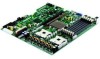
Hardware Installations and Upgrades 8. Lift the heat sink from the processor. If it does not pull up easily, twist the heat sink again. Do not force the heat sink from the processor. Doing so could damage the processor. 9. Lift the processor lever. 10. Remove the processor. 11. If installing a replacement processor, see "Installing the Processor." Otherwise, reinstall the chassis cover. RJ45 Serial Port Configuration The RJ45 serial port connector can be configured to support either a DSR signal or a DCD signal. As the server board is shipped, it is configured to support DSR signals. To change the configuration to support DCD signals a jumper on the board must be changed. Use the following instructions to configure your server board to support DCD signals. 1. Observe the safety and ESD precautions at the beginning of this book. 2. Turn off all peripheral devices connected to the server. Turn off the server. 3. Disconnect the AC power cord from the server. 4. Remove the server's cover. See the documentation that accompanied your server chassis for instructions on removing the server's cover. 5. Locate the jumper block for the serial port. See Figure 12. 6. Move the jumper from the default position covering pins 1 and 3 to cover pins 2 and 4. J8A3 34 1-3: DCD to DTR (Default) 2-4: DSR to DTR 2 TP00944 Figure 12. Changing the Serial Port Configuration 31
-
 1
1 -
2
-
3
-
4
-
5
-
6
-
7
-
8
-
9
-
10
-
11
-
12
-
13
-
14
-
15
-
16
-
17
-
18
-
19
-
20
-
21
-
22
-
23
-
24
-
25
-
 26
26 -
 27
27 -
 28
28 -
 29
29 -
 30
30 -
 31
31 -
 32
32 -
 33
33 -
 34
34 -
 35
35 -
 36
36 -
37
-
38
-
39
-
40
-
41
-
42
-
43
-
44
-
45
-
46
-
47
-
48
-
49
-
50
-
51
-
52
-
53
-
54
-
55
-
56
-
57
 |
 |
