Intel SE7501CW2 Product Guide - Page 60
The 400 MHz Intel Xeon processor and the 533 MHz Intel Xeon processor, NOTES
 |
UPC - 735858160308
View all Intel SE7501CW2 manuals
Add to My Manuals
Save this manual to your list of manuals |
Page 60 highlights
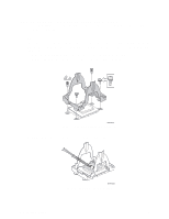
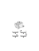
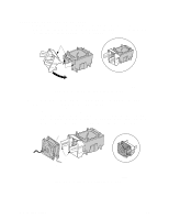
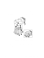
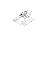
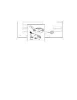
3. Align the heat sink over the processor and set it into place. If your heat sink has a flat end on it, the flat end must point toward the rear of the chassis. 4. Position the retention mechanism clips over the plastic tabs at the center of the retention mechanism. Note that the slot in the clip provides room for side-to-side motion. Push down on the top of each retention clip while sliding it to over. (Figure 15, 1). 5. Engage each end of the retention mechanism clips over the plastic tabs at the sides of the retention mechanism (Figure 15, 2). 6. Press downward on the ends of the retention mechanism clips to lock them into place over the plastic tabs (Figure 15, 3 and 4). ✏ NOTES The 400 MHz Intel Xeon processor and the 533 MHz Intel Xeon processor use different retention mechanism clips. Although the clips appear to be nearly identical, they vary slightly in size. Use only the clips that came with your processor. For both the 400 MHz clips and the 533 MHz clips, make sure the center tab on the clip engages in the heat sink base. A C B C E 1 3 D 2 4 TP00099 Figure 15. Attaching the Heat Sink and Retention Clip 60 Intel Server Board SE7501CW2 Product Guide
-
 1
1 -
2
-
3
-
4
-
5
-
6
-
7
-
8
-
9
-
10
-
11
-
12
-
13
-
14
-
15
-
16
-
17
-
18
-
19
-
20
-
21
-
22
-
23
-
24
-
25
-
26
-
27
-
28
-
29
-
30
-
31
-
32
-
33
-
34
-
35
-
36
-
37
-
38
-
39
-
40
-
41
-
42
-
43
-
44
-
45
-
46
-
47
-
48
-
49
-
50
-
51
-
52
-
53
-
54
-
 55
55 -
 56
56 -
 57
57 -
 58
58 -
 59
59 -
 60
60 -
 61
61 -
 62
62 -
 63
63 -
 64
64 -
 65
65 -
66
-
67
-
68
-
69
-
70
-
71
-
72
-
73
-
74
-
75
-
76
-
77
-
78
-
79
-
80
-
81
-
82
-
83
-
84
-
85
-
86
-
87
-
88
-
89
-
90
-
91
-
92
-
93
 |
 |
