Invacare 3GTQ-MCG Owners Manual
Invacare 3GTQ-MCG Manual
 |
View all Invacare 3GTQ-MCG manuals
Add to My Manuals
Save this manual to your list of manuals |
Invacare 3GTQ-MCG manual content summary:
- Invacare 3GTQ-MCG | Owners Manual - Page 1
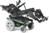
3G Storm Series® Invacare 3G Storm Series Arrow® Invacare 3G Storm Series Ranger X™ Invacare 3G Storm Series Torque™ SP Invacare 3G Storm Series Torque SE Invacare 3G Storm Series Torque 3 Power Wheelchair Base User Manual EN This manual MUST be given to the user of the product. BEFORE using - Invacare 3GTQ-MCG | Owners Manual - Page 2
or modification in whole or in part is prohibited without prior written permission from Invacare. Trademarks are identified by ™ and ®. All trademarks are owned by or licensed to Invacare Corporation or its subsidiaries unless otherwise noted. Invacare 3G Storm Series® 2 Part No 1143151 - Invacare 3GTQ-MCG | Owners Manual - Page 3
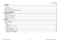
17 Wheelchairs without TRRO ...18 3 SAFETY 19 General Guidelines ...19 Operation Information ...20 Setup ...20 Transport...21 Repair or Service Information ...23 Safety/Handling ...24 A Note to Wheelchair Assistants...25 Stability and Balance ...26 Coping with Everyday Obstacles...29 Footplates - Invacare 3GTQ-MCG | Owners Manual - Page 4
30 Transferring To and From Other Seats...31 Storage...32 Electrical - Grounding Instructions...33 Batteries ...33 Tire Pressure ...34 Weight Training...35 Shipping Securement Points 38 Seat...39 Wheels ...39 Batteries ...40 Driving ...40 Weight...41 Invacare 3G Storm Series® 4 Part No 1143151 - Invacare 3GTQ-MCG | Owners Manual - Page 5
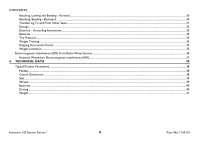
Speed Control Buttons...46 Joystick ...47 Charger/Programming Input...47 Information Gauge Display ...47 Service Indicator ...47 CMPJ+ Joystick Switches and Indicators...48 On/Off - Drive Select Toggle and SPJ+ w/ACC Joysticks...57 CMPJ+ Joystick ...57 Part No 1143151 5 Invacare 3G Storm Series® - Invacare 3GTQ-MCG | Owners Manual - Page 6
Securement Points...70 Securing the Wheelchair...70 Securing the Occupant ...71 Wheelchair-Anchored Belts...71 Vehicle-Anchored Belts...73 Seating System ...73 Positioning Belts ...74 Invacare 3G Storm Series® 6 Part No 1143151 - Invacare 3GTQ-MCG | Owners Manual - Page 7
...77 Inspect/Adjust Weekly...77 Inspect/Adjust Monthly...78 Inspect/Adjust Periodically...78 Service Inspection ...79 Six Month Inspection ...79 Inspect/Adjust Every 18 Months...81 Batteries Box Retaining Strap - 22NF Battery Base Frames ...103 Part No 1143151 7 Invacare 3G Storm Series® - Invacare 3GTQ-MCG | Owners Manual - Page 8
...108 Adjusting the Extended Active Anti-Tippers...109 Disconnecting/Connecting the Joysticks ...111 SPJ+ Joysticks ...111 CMPJ+ Joysticks ...112 9 TROUBLESHOOTING 113 Driving Performance ...113 Electrical ...113 SPJ+, SPJ+ w/PSS or SPJ+ w/ACC Joysticks...113 CMPJ+, PSR+, PSF+ Joysticks or - Invacare 3GTQ-MCG | Owners Manual - Page 9
1 GENERAL 1.1 Symbols Warnings Signal words are used in this manual and apply to hazards or unsafe practices which could result in personal it is not avoided. Gives useful tips, recommendations and information for efficient, trouble-free use. Part No 1143151 9 Invacare 3G Storm Series® - Invacare 3GTQ-MCG | Owners Manual - Page 10
referenced in this manual. MK6i™ Electronics Programming Guide Adjustable ASBA Owner's Manual 3G Storm Series Base Service Manual Van Seat Owner's Manual Formula™ CG Seating System Adjustable ASBA Service Manual MANUAL PART NUMBER 1141471 1143192 1104849 1143195 1143155 1143238 Invacare 3G Storm - Invacare 3GTQ-MCG | Owners Manual - Page 11
shall be limited to such repair and/or replacement. For warranty service, please contact the dealer from whom you purchased your Invacare product. In the event you do not receive satisfactory warranty service, please write directly to Invacare at the address on the bottom of the back cover. Provide - Invacare 3GTQ-MCG | Owners Manual - Page 12
shall be limited to such repair and/or replacement. For warranty service, please contact the dealer from whom you purchased your Invacare product. In the event you do not receive satisfactory warranty service, please write directly to Invacare at the address on the bottom of the back cover. Provide - Invacare 3GTQ-MCG | Owners Manual - Page 13
inside of the battery box lids. Group 24 Batteries Only 22NF Batteries Only Rear Battery Box Lid Front Battery Box Lid Part No 1143151 13 Invacare 3G Storm Series® - Invacare 3GTQ-MCG | Owners Manual - Page 14
2 LABEL LOCATIONS Gearless Brushless GB™Motors with Group 24 Batteries Only 4 Pole Motors with Group 24 Batteries Only Elevate Systems with Group 24 Batteries Only Invacare 3G Storm Series® 14 Part No 1143151 - Invacare 3GTQ-MCG | Owners Manual - Page 15
near the front of the wheelchair. Suspension Arm Used with Conventional Motor/ Gearbox Assembly Suspension Arm Used with Standard GB Motor Part No 1143151 15 Invacare 3G Storm Series® - Invacare 3GTQ-MCG | Owners Manual - Page 16
2 LABEL LOCATIONS Suspension Arm Used with GB Motor Shown 2.2 Wheelchairs with O2 Holders ASBA Seats DRIVE PUSH Captain's Seats P/N 1114835 Invacare 3G Storm Series® 16 Part No 1143151 - Invacare 3GTQ-MCG | Owners Manual - Page 17
2.3 Wheelchairs with TRRO Also on opposite side. 2 LABEL LOCATIONS Also on opposite side. Also on opposite side. Part No 1143151 17 Invacare 3G Storm Series® - Invacare 3GTQ-MCG | Owners Manual - Page 18
2 LABEL LOCATIONS 2.4 Wheelchairs without TRRO Auto style seat positioning strap shown. This label is also on the airline style seat positioning strap. Invacare 3G Storm Series® 18 Part No 1143151 - Invacare 3GTQ-MCG | Owners Manual - Page 19
these instructions and any additional instructional material such as owner's manuals, service manuals or instruction sheets supplied Invacare and are not recommended for use with Invacare products. DO NOT connect any medical devices such as ventilators, life support machines, etc., directly - Invacare 3GTQ-MCG | Owners Manual - Page 20
of this wheelchair. Also, a qualified technician must perform all procedures in the service manual. Performance adjustments should only be made by professionals of the healthcare field or this procedure until the wheelchair performs to specifications. Invacare 3G Storm Series® 20 Part No 1143151 - Invacare 3GTQ-MCG | Owners Manual - Page 21
included with TRRO or TRBKTS for the purposes described in this manual. TRRO (Transport Ready Option) - TRRO includes four factory-installed available by the auto industry. Invacare cannot and does not recommend any wheelchair transportation systems. Battery support brackets MUST be installed at - Invacare 3GTQ-MCG | Owners Manual - Page 22
is necessary to move an unoccupied power wheelchair up or down the stairs. Invacare recommends using two assistants and making thorough preparations. Make sure to use ONLY secure, non-detachable parts for hand-hold supports. DO NOT use an escalator to move a wheelchair between floors. Serious bodily - Invacare 3GTQ-MCG | Owners Manual - Page 23
the owner's operator and maintenance manual, (2) the service manual (if applicable) and (3) the seating system's manual (if applicable). if you are unable to understand the warnings, cautions and instructions, contact Invacare technical support before attempting to service or operate this equipment - Invacare 3GTQ-MCG | Owners Manual - Page 24
only as a "basic" guide. The techniques that are discussed on the following pages have been used successfully by many. Individual wheelchair users often develop skills to deal with daily living activities that may differ from those described in this manual. Invacare recognizes and encourages each - Invacare 3GTQ-MCG | Owners Manual - Page 25
direction you are turning. DO NOT shift your weight in the opposite direction of the turn. Shifting your weight in the opposite direction sitting position toward the direction you are reaching as a qualified technician for instructions. DO NOT attempt to wheelchair or as lifting supports, as they may - Invacare 3GTQ-MCG | Owners Manual - Page 26
. Doing so will reduce traction and increase stopping distance. DO NOT leave elevating legrests in the fully extended position when proceeding down ramps or slopes. Invacare 3G Storm Series® 26 Part No 1143151 - Invacare 3GTQ-MCG | Owners Manual - Page 27
and distributes additional weight on rear wheels. The forward mounting position is not available on Arrow wheelchairs equipped with GB motors. Part No 1143151 27 Invacare 3G Storm Series® - Invacare 3GTQ-MCG | Owners Manual - Page 28
GB motors. Motor Mounting Positions Motor Mounting Positions Motor Mounting Positions Rear Position (Standard) Approximately 65% of weight over drive wheels Invacare 3G Storm Series® Middle Position (1 inch Forward) Approximately 70% of weight over drive wheels FIGURE 1 Stability and Balance 28 - Invacare 3GTQ-MCG | Owners Manual - Page 29
the wheelchair, make sure that the footplates are in the upward position or swing footrests towards the outside of the wheelchair. Part No 1143151 29 Invacare 3G Storm Series® - Invacare 3GTQ-MCG | Owners Manual - Page 30
or bending only as far as your arm will extend without changing your sitting position. FIGURE 2 Reaching, Leaning and Bending - Forward FIGURE 3 Reaching, Bending - Backward Invacare 3G Storm Series® 30 Part No 1143151 - Invacare 3GTQ-MCG | Owners Manual - Page 31
or without wheel locks.) transfer to and from the wheelchair in the presence of a qualified healthcare professional to determine individual safety limits. Invacare strongly recommends ordering the wheel locks as an additional safeguard for the wheelchair user. For this procedure, refer to FIGURE - Invacare 3GTQ-MCG | Owners Manual - Page 32
combustible products. Serious injury or damage to property may result. Invacare has tested its power wheelchairs in accordance with ISO 7176 " leave power wheelchair in a damp area for any length of time. Direct exposure to rain or dampness will cause the wheelchair to malfunction electrically and - Invacare 3GTQ-MCG | Owners Manual - Page 33
Instructions ƽ WARNING DO NOT, under any circumstances, cut or remove the round grounding prong from any plug used with or for Invacare the device being connected. In addition, Invacare has placed RED/ORANGE warning tags on manual are based on the use of deep cycle gel cell batteries. Invacare - Invacare 3GTQ-MCG | Owners Manual - Page 34
WARNING NEVER attempt to recharge the batteries by attaching cables directly to the battery terminals. DO NOT attempt to recharge the the manufacturer's instructions for each charger (supplied or purchased). If charging instructions are not supplied Invacare 3G Storm Series® 34 Part No 1143151 - Invacare 3GTQ-MCG | Owners Manual - Page 35
have NOT been designed or tested as a seat for any kind of weight training. If occupant uses said wheelchair as a weight training apparatus, INVACARE SHALL NOT BE LIABLE FOR BODILY INJURY AND THE WARRANTY IS VOID. Shipping Securement Points ƽ WARNING Frame end caps are only intended for - Invacare 3GTQ-MCG | Owners Manual - Page 36
powered wheelchair to release its brakes, move by itself, or move in unintended directions. It can also permanently damage the powered wheelchair's control system. The intensity of know, are not likely to cause EMI problems to your powered wheelchair. Invacare 3G Storm Series® 36 Part No 1143151 - Invacare 3GTQ-MCG | Owners Manual - Page 37
20 volts per meter. 3) The immunity level of the product is unknown. Modification of any kind to the electronics of this scooter as manufactured by Invacare may adversely affect the EMI immunity levels. Part No 1143151 37 - Invacare 3GTQ-MCG | Owners Manual - Page 38
: Minimum: Maximum 3GAR, 3GAR-CG, 3GARBASE 3GTQSPBASE, 3GTQSP, 3GTQ-CG, 3GTQ-MCG, 3GTQ3-MCG 3GTQ3, 3GTQ3V, 3GTQ3-CG, 3GTQ3-MCG 3GRX, 3GRXBASE, 3GRX-CG ARROW TORQUE SP TORQUE 3 25 inches 29.5 inches 32.5 inches 34.25 inches 34.25 inches 44.25 inches RANGER X Invacare 3G Storm Series® 38 - Invacare 3GTQ-MCG | Owners Manual - Page 39
Standard, Shock Fork (optional) 14 x 3 inch 14 x 4 inch Adjustable (Non-recliners Only) 3 inch wheels RANGER X 8 x 2.25 inch 6 x 2 inch 8 x 2 inch 9 x 2.75 inch Part No 1143151 39 Invacare 3G Storm Series® - Invacare 3GTQ-MCG | Owners Manual - Page 40
joystick to determine the range of their wheelchair. Refer to When to Charge Batteries on page 56 for more information about the battery discharge indicator. Invacare 3G Storm Series® 40 Part No 1143151 - Invacare 3GTQ-MCG | Owners Manual - Page 41
equal 25 lbs, subtract 25 lbs from 300 lbs this means the maximum weight limitation of the user is 275 lbs. Part No 1143151 41 Invacare 3G Storm Series® - Invacare 3GTQ-MCG | Owners Manual - Page 42
WHEELCHAIR OPERATION 5 Wheelchair Operation ƽ WARNING After ANY adjustments, repair or service and before use, make sure that all attaching hardware is tightened securely position. Press the On/Off button. FIGURE 1 Turning the Power On/Off Invacare 3G Storm Series® 42 Part No 1143151 - Invacare 3GTQ-MCG | Owners Manual - Page 43
slow the wheelchair to a stop, simply release the joystick. The wheelchair has automatic speed and direction compensation to minimize corrections. When first learning to drive, select a slow speed and try to the joystick in the following manner: Part No 1143151 43 Invacare 3G Storm Series® - Invacare 3GTQ-MCG | Owners Manual - Page 44
these procedures: • SPJ+, MK6i™ SPJ+ w/PSS and MK6i SPJ+ w/ACC Joystick Switches and Indicators on page 45. • CMPJ+ Joystick Switches and Indicators on page 48. Invacare 3G Storm Series® 44 Part No 1143151 - Invacare 3GTQ-MCG | Owners Manual - Page 45
Tortoise) GREEN LED Information Gauge Display Mode Button* Speedometer Increase Speed Button (Hare) Service Indicator *The mode button is only present on SPJ+ w/ACC joystick. Additional + w/PSS and MK6i SPJ+ w/ACC Joystick Switches and Indicators Part No 1143151 45 Invacare 3G Storm Series® - Invacare 3GTQ-MCG | Owners Manual - Page 46
• Press and hold the tortoise button ( bars in the speedometer will light. ) or hare button ( ) to decrease/increase the speed in smaller increments. The smaller Invacare 3G Storm Series® 46 Part No 1143151 - Invacare 3GTQ-MCG | Owners Manual - Page 47
joystick. The wheelchair has automatic speed and direction compensation to minimize corrections. Charger/Programming housing. This provides easy access for charging the wheelchair batteries Service Indicator The AMBER service indicator will light when an error or fault occurs. Refer to Service - Invacare 3GTQ-MCG | Owners Manual - Page 48
Display Mode Switch Speed Control Knob Programmable Mono Port 1/2 or External Mode Switch Remote On/ Off Input To Controller FIGURE 4 CMPJ+ Joystick Switches and Indicators Invacare 3G Storm Series® 48 Part No 1143151 - Invacare 3GTQ-MCG | Owners Manual - Page 49
simply release the joystick. The wheelchair has automatic speed and direction compensation to minimize corrections. Charger/Programming Input The charger/ front of the joystick housing. This provides easy access for charging the wheelchair batteries. This port 1143151 49 Invacare 3G Storm Series® - Invacare 3GTQ-MCG | Owners Manual - Page 50
via the programmer. This symbol shows the Battery Level and will change depending on the available battery power. This indicator is shown on every screen. Invacare 3G Storm Series® 50 Part No 1143151 - Invacare 3GTQ-MCG | Owners Manual - Page 51
OPERATION ITEM STATUS MESSAGE CLOCK STATUS INDICATOR MODES This area displays status or instructions. DESCRIPTION Displays current time. The status indicator will show a "Warning" to ECU Output Activated ASM 1 ASM 2 Part No 1143151 Infrared Mouse 51 Mouse B Invacare 3G Storm Series® - Invacare 3GTQ-MCG | Owners Manual - Page 52
screen was highlighted. The Drive's name, warning/info message, status icon and battery indicator are displayed on this screen. FIGURE 7 LCD Display Screens - Driving Screen Invacare 3G Storm Series® 52 Part No 1143151 - Invacare 3GTQ-MCG | Owners Manual - Page 53
move the joystick forward to enter new date and time. BATTERY VOLTAGE - Displays current battery voltage. This is a diagnostic test a user can perform prior to a service call. FAULT CODES - Displays time and date stamped fault codes. This information can be helpful to a provider prior to making - Invacare 3GTQ-MCG | Owners Manual - Page 54
Actuators Generic Right Leg Actuator Generic Left Leg Actuator Intelligent CG Tilt Shark Power Module (SPM) Actuator SANODE or Single Actuator ICON DESCRIPTION Generic Analog Control This is displayed if the controller supports G-Trac Mouse Only IR/Mouse Digital Attendant Control Micro Extremity - Invacare 3GTQ-MCG | Owners Manual - Page 55
switch must be in the On position. Each activation of the ability switch will alternately turn the joystick On or Off. Part No 1143151 55 Invacare 3G Storm Series® - Invacare 3GTQ-MCG | Owners Manual - Page 56
, DO NOT allow battery charge to empty. If battery charge becomes so low that no battery indicators are lit, allow the batteries to charge overnight. Invacare 3G Storm Series® 56 Part No 1143151 - Invacare 3GTQ-MCG | Owners Manual - Page 57
FIGURE 9 SPJ+, SPJ+ w/PSS and SPJ+ w/ACC Joysticks Display Screen Battery Gage Display Batteries Empty Batteries Full FIGURE 10 CMPJ+ Joystick Part No 1143151 57 Invacare 3G Storm Series® - Invacare 3GTQ-MCG | Owners Manual - Page 58
Charging Batteries ƽ WARNING NEVER attempt to recharge the batteries by attaching cables directly to the battery terminals or clamps. ALWAYS use the recharging plug located on . Extensive use on inclines may substantially reduce per charge mileage. Invacare 3G Storm Series® 58 Part No 1143151 - Invacare 3GTQ-MCG | Owners Manual - Page 59
be charged. Refer to owner's manual shipped with battery charger. ƽ Invacare dealer. If performing the charging procedures, READ and CAREFULLY follow the individual instructions for each charger (supplied or purchased). If charging instructions are not supplied, consult a qualified service - Invacare 3GTQ-MCG | Owners Manual - Page 60
batteries need to be charged more often or take longer to charge than normal, they may need to be replaced. Contact an Invacare dealer for service. SPJ+, SPJ+ w/PSS and SPJ+ w/ACC Joysticks Charger/ Programming Port CMPJ+ Joystick Charger/ Programming Port (On Front of Joystick) Display Charger - Invacare 3GTQ-MCG | Owners Manual - Page 61
to 30 pounds*. Force to operate motor lock lever exceeds ANSI/RESNA WC/VOL2-1998 requirements for section 14.7 paragraph 7.2d. Part No 1143151 61 Invacare 3G Storm Series® - Invacare 3GTQ-MCG | Owners Manual - Page 62
Lever Towards Outside of Wheelchair ENGAGE (Drive) Motor Lock Lever FIGURE 12 Disengaging/Engaging Motor Lock Levers P/N1114835 DRIVE PUSH DISENGAGE (Push) Motor Lock Lever Invacare 3G Storm Series® 62 Part No 1143151 - Invacare 3GTQ-MCG | Owners Manual - Page 63
. 2. Repeat STEP 1 for opposite wheel. Wheel Lock DISENGAGE ENGAGE Wheel Lock Handle Drive Wheel FIGURE 13 Disengaging/Engaging the Wheel locks Part No 1143151 63 Invacare 3G Storm Series® - Invacare 3GTQ-MCG | Owners Manual - Page 64
adjustments, repair or service and before use, make sure that all attaching hardware is tightened securely otherwise injury or damage may result. CAUTION As with any vehicle, the wheels and tires should be checked periodically for cracks and wear, and should be replaced. Invacare 3G Storm Series - Invacare 3GTQ-MCG | Owners Manual - Page 65
place (Detail "B"). DETAIL "A" - DISENGAGE Pins Engagement Knob Free Wheel Detents DETAIL "B" - ENGAGE Engagement Knob Wheel Hubs Part No 1143151 FIGURE 1 Using Optional Wheel Hubs 65 Invacare 3G Storm Series® - Invacare 3GTQ-MCG | Owners Manual - Page 66
with TRRO (Transport Ready Option). Contact Invacare Corporation (800-333-6900) with any which meet the requirements of the SAE (Society of Automotive Engineers) J2249 Recommended Practice items should be removed and secured separately. Postural supports, positioning devices, and/or belt(s) should - Invacare 3GTQ-MCG | Owners Manual - Page 67
. To maintain compliance, refer to wheelchair service manual before making any adjustments. DO NOT alter existing models and are not field serviceable. Battery support brackets MUST be installed at moving vehicle of any type. It is Invacare's position that users of wheelchairs should be transferred - Invacare 3GTQ-MCG | Owners Manual - Page 68
Test) ANSI = American National Standards Institute RESNA= Rehabilitation Engineering and Assistive Technology Society of North America This wheelchair has been dynamically tested in a forward-facing mode with to 300 lbs N/A Up to 300 lbs N/A Invacare 3G Storm Series® 68 Part No 1143151 - Invacare 3GTQ-MCG | Owners Manual - Page 69
for a tall adult male . (Frontal Clear Zone) 16in. FCZ Side View 8in. 8in. HHT 16in. FCZ (Frontal Clear Zone) Top View Part No 1143151 69 Invacare 3G Storm Series® - Invacare 3GTQ-MCG | Owners Manual - Page 70
Occupant Restraint Systems (WTORS) that have been installed in accordance with the manufacturer's instructions and SAE J2249. A copy of SAE J2249 Wheelchair Tie-down and brackets in accordance with the manufacturer's instructions and SAE J2249. Invacare 3G Storm Series® 70 Part No 1143151 - Invacare 3GTQ-MCG | Owners Manual - Page 71
belt which meets the requirements of ANSI/RESNA WC/19. The pelvic belt provided by Invacare has been designed to accommodate use on either side of the vehicle. If necessary, follow the instructions below to reverse the orientation of the pelvic belt to accommodate the vehicle-anchored upper torso - Invacare 3GTQ-MCG | Owners Manual - Page 72
Male End Small End of Slot DETAIL "C" - JUNIOR SEATS Large End of Slot Belt Mounting Bracket Pin (Used to secure the vehicleanchored upper torso belt.) Invacare 3G Storm Series® FIGURE 2 Wheelchair-Anchored Belts 72 Small End of Slot Part No 1143151 - Invacare 3GTQ-MCG | Owners Manual - Page 73
) vehicle-installed restraint system Ensure that the factory installed seating system is secured to the wheelchair frame before operation. Refer to the seating system owner's manual. Part No 1143151 73 Invacare 3G Storm Series® - Invacare 3GTQ-MCG | Owners Manual - Page 74
belt angles are especially important if the pelvic belt is intended to be used for postural support in addition to occupant restraint in a frontal crash. Steeper angles will reduce the tendency for 75. Preferred Zone Optional Zone Side View 45° 30° 75° Invacare 3G Storm Series® 74 Part No 1143151 - Invacare 3GTQ-MCG | Owners Manual - Page 75
comfort. DO position belts INSIDE of armrests, wheels, etc. DO NOT position belts OUTSIDE of armrests, wheels, etc. FIGURE 4 Positioning Belts Part No 1143151 75 Invacare 3G Storm Series® - Invacare 3GTQ-MCG | Owners Manual - Page 76
as necessary, take your wheelchair to a qualified technician for a thorough inspection and servicing. Refer to Service Inspection on page 79. Check all parts for shipping damage. In case of powered functions (Example: drive, seating and legrests). Invacare 3G Storm Series® 76 Part No 1143151 - Invacare 3GTQ-MCG | Owners Manual - Page 77
necessary, take your wheelchair to a qualified technician for a thorough inspection and servicing. Service Inspection on page 79. Weekly, monthly and periodic inspections should be performed by powered functions (Example: drive, seating and legrests). Part No 1143151 77 Invacare 3G Storm Series® - Invacare 3GTQ-MCG | Owners Manual - Page 78
a qualified technician. Check center mount front riggings for loose fasteners. Replace /tighten if necessary. Check that all labels are present and legible. Replace if necessary. Invacare 3G Storm Series® 78 Part No 1143151 - Invacare 3GTQ-MCG | Owners Manual - Page 79
the service inspection may vary according to the specific wheelchair: Six Month Inspection Clean upholstery and armrests. Clean dirt and lint from axles. Clean dirt and lint from bearings. Check that all labels are present and legible. Replace if necessary. Part No 1143151 79 Invacare 3G - Invacare 3GTQ-MCG | Owners Manual - Page 80
DO NOT interfere with tires when rolling. Ensure wheel lock pivot point are free of wear and looseness. Ensure wheel locks are easy to engage. Invacare 3G Storm Series® 80 Part No 1143151 - Invacare 3GTQ-MCG | Owners Manual - Page 81
straps and/or loose fasteners. If found, replace these items. Inspect/Adjust Every 18 Months Replace motor brushes and gearbox coupling. Part No 1143151 81 Invacare 3G Storm Series® - Invacare 3GTQ-MCG | Owners Manual - Page 82
use of rubber gloves is recommended when working with batteries. Invacare strongly recommends that battery installation and battery replacement ALWAYS be done by a qualified technician. After ANY adjustments, repair or service and before use, make sure all attaching hardware is tightened securely - Invacare 3GTQ-MCG | Owners Manual - Page 83
/Post NEGATIVE (+) Battery Terminal/Post POSITIVE (+) Battery Terminal/Post DETAIL "A" - TERMINAL CROSS HOLES Terminal Cross Holes 22NF 22NF DO NOT Use Part No 1143151 83 Invacare 3G Storm Series® - Invacare 3GTQ-MCG | Owners Manual - Page 84
CROSS NEGATIVE (+) Battery Terminal/Post POSITIVE (+) Battery Terminal/Post Battery Terminal/Post NEGATIVE (+) Battery Terminal/Post HOLES Terminal Cross Holes GP24 GP24 DO NOT Use Invacare 3G Storm Series® 84 Part No 1143151 - Invacare 3GTQ-MCG | Owners Manual - Page 85
damage to your wheelchair and give you unsatisfactory performance. The warranty and performance specifications contained in this manual are based on the use of deep cycle gel cell batteries. Invacare strongly recommends their use as the power source for this unit. Both battery sizes are deep - Invacare 3GTQ-MCG | Owners Manual - Page 86
8 SETUP/MAINTENANCE 8.7 Replacing Batteries Invacare recommends that both batteries be replaced if one battery is defective. 1. Remove the battery box(es) to carpeting or floor covering. 2. Verify the joystick On/Off switch is in the Off position. Invacare 3G Storm Series® 86 Part No 1143151 - Invacare 3GTQ-MCG | Owners Manual - Page 87
assembly with guide pins facing the inside of the wheelchair. 5. Slide along the sub-frame until its guide pins are engaged in the sub- not interfere with the one connector battery box guide pins when engaging the connector on the one guide pins are engaged in the connector of the two - Invacare 3GTQ-MCG | Owners Manual - Page 88
secure the shocks to the base frame. ƽ WARNING Wheelchairs with TRRO or TRBKTS Only - Battery support brackets MUST be installed at all times. Otherwise, the wheelchair will not be WC/19 compliant. using three bolts and washers. Torque to 13 ft-lbs. Invacare 3G Storm Series® 88 Part No 1143151 - Invacare 3GTQ-MCG | Owners Manual - Page 89
No 1143151 Lower Battery Retainer Bracket Bolts and Washers Front Battery Retainer Bracket FIGURE 1 Removing/Installing Battery Boxes - Group 24 Wheelchairs without Vent Tray 89 Invacare 3G Storm Series® - Invacare 3GTQ-MCG | Owners Manual - Page 90
Battery Box Sub-Frame Two Connector Battery Box Base Frame One Connector Battery Box Battery Box Retainer Bar FIGURE 2 Group 24 Wheelchairs with Vent Tray Invacare 3G Storm Series® 90 Part No 1143151 - Invacare 3GTQ-MCG | Owners Manual - Page 91
carrying strap is positioned on top of the battery box and will not interfere with the one battery box guide pins when engaging the connector on the one battery box lid. 6. Secure the battery box carrying strap is securely clipped (locked) into place. Part No 1143151 91 Invacare 3G Storm Series® - Invacare 3GTQ-MCG | Owners Manual - Page 92
the open position. 7. Remove battery box cover from the battery box. Arrows Battery Box Battery Box Retention Strap FIGURE 3 Removing/Installing the 22NF Battery Box Invacare 3G Storm Series® 92 Part No 1143151 - Invacare 3GTQ-MCG | Owners Manual - Page 93
tip the batteries. Keep the batteries in an upright position. The warranty and performance specifications contained in this manual are based on the use of deep cycle gel cell batteries. Invacare strongly recommends their use as the power source for this unit. CAUTION Place the wheelchair in a well - Invacare 3GTQ-MCG | Owners Manual - Page 94
. ƽ CAUTION Some battery manufacturers mold a carrying strap and/or hold down flanges directly into the battery case. Batteries which interfere with the battery box cannot be used for . FIGURE 4 Installing/Removing Batteries Into/From Battery Boxes Invacare 3G Storm Series® 94 Part No 1143151 - Invacare 3GTQ-MCG | Owners Manual - Page 95
Cleaning Battery Terminals 8 SETUP/MAINTENANCE ƽ WARNING Most batteries are not sold with instructions. However, warnings are frequently noted on the cell caps. Read them carefully. DO be shiny, not dull. 4. Carefully dust off all metal particles. Part No 1143151 95 Invacare 3G Storm Series® - Invacare 3GTQ-MCG | Owners Manual - Page 96
(Detail "A" of FIGURE 6) 4. Remove the locknut and fuse mounting screw or clamp to disconnect RED battery cable from the POSITIVE (+) battery post (Detail "A" of FIGURE 6). Invacare 3G Storm Series® 96 Part No 1143151 - Invacare 3GTQ-MCG | Owners Manual - Page 97
, otherwise the life of the batteries will be reduced 9. If necessary, charge the batteries. Refer to Charging Batteries on page 58. Part No 1143151 97 Invacare 3G Storm Series® - Invacare 3GTQ-MCG | Owners Manual - Page 98
/Post RED BLACK Battery Terminal Cap POSITIVE (+) Battery Cable POSITIVE (+) Battery Terminal/Post Top View of Battery FIGURE 5 Disconnecting/Connecting Battery Cables - Group 24 Batteries Invacare 3G Storm Series® 98 Part No 1143151 - Invacare 3GTQ-MCG | Owners Manual - Page 99
/Post RED Battery Terminal Cap NEGATIVE (-) Battery Terminal/Post Part No 1143151 FIGURE 6 Disconnecting/Connecting Battery Cables - Group 24 Batteries Top View of Battery 99 Invacare 3G Storm Series® - Invacare 3GTQ-MCG | Owners Manual - Page 100
before using, otherwise the life of the batteries will be reduced 10. If necessary, charge the battery(ies). Refer to Charging Batteries on page 58. Invacare 3G Storm Series® 100 Part No 1143151 - Invacare 3GTQ-MCG | Owners Manual - Page 101
Rear Battery REAR 8 SETUP/MAINTENANCE DETAIL "A" Terminal Cap Terminal End Part No 1143151 FIGURE 7 Disconnecting/Connecting Battery Cables - 22NF Batteries in Single Battery Box 101 Invacare 3G Storm Series® - Invacare 3GTQ-MCG | Owners Manual - Page 102
Box Bottom Battery Box Top Battery box top cut away for clarification purposes only. FIGURE 8 Disconnecting/Connecting Battery Cables - 22NF Batteries in Single Battery Box Invacare 3G Storm Series® 102 Part No 1143151 - Invacare 3GTQ-MCG | Owners Manual - Page 103
wheelchair. Battery Box Tray Slot Folded Over Portion of Retaining Strap FIGURE 9 Replacing Battery Box Retaining Strap - 22NF Battery Base Frames Part No 1143151 103 Invacare 3G Storm Series® - Invacare 3GTQ-MCG | Owners Manual - Page 104
locks.) - transfer to and from the wheelchair in the presence of a qualified healthcare professional to determine individual safety limits. Invacare strongly recommends ordering the wheel locks as an additional safeguard for the wheelchair user. Wheel Lock Installation Identification 1. Examine - Invacare 3GTQ-MCG | Owners Manual - Page 105
Standard 2 in Forward 1 in Forward FIGURE 11 Installing Wheel Locks for Motor/Gearbox Assemblies Use this side of mounting hole only. Part No 1143151 105 Invacare 3G Storm Series® - Invacare 3GTQ-MCG | Owners Manual - Page 106
(1" Forward Standard) Motor Position Mounting Holes for Rear Motor Position Washers Hex Screws Wheel Lock FIGURE 12 Installing Wheel Locks for GB Motors Mounting Bracket Invacare 3G Storm Series® 106 Part No 1143151 - Invacare 3GTQ-MCG | Owners Manual - Page 107
Wheel Lock Shoe 5/32 to 5/16 - inch Gap Illustration depicts wheel lock for motor/gearbox assembly. FIGURE 13 8.14Adjusting Wheel Locks Part No 1143151 107 Invacare 3G Storm Series® - Invacare 3GTQ-MCG | Owners Manual - Page 108
the caster headtube. Locknut Components exploded for clarity. Fork There is no need to remove the fork from the base frame. FIGURE 14 Adjusting Forks Invacare 3G Storm Series® 108 Part No 1143151 - Invacare 3GTQ-MCG | Owners Manual - Page 109
assembly. 6. Remove ¼-inch block. 7. Repeat STEPS 1-6 for the remaining anti-tip assembly. 8. Install the dust cover onto each anti-tip assembly. Part No 1143151 109 Invacare 3G Storm Series® - Invacare 3GTQ-MCG | Owners Manual - Page 110
A DETAIL B Standard AntiTippers Install Dust Cover Here Locknut C Bearings Locknut A Locknut B Extended Active Anti-Tippers Extended Active Anti-Tipper Assembly Wheel ¼-Inch Block Ground/Floor Invacare 3G Storm Series® FIGURE 15 Adjusting the Extended Active Anti-Tippers 110 Part No 1143151 - Invacare 3GTQ-MCG | Owners Manual - Page 111
. 2. Lightly push to engage the joystick connector and the controller connector. Joystick Connector FIGURE 16 Disconnecting/Connecting the Joysticks - SPJ+ Joysticks Part No 1143151 111 Invacare 3G Storm Series® - Invacare 3GTQ-MCG | Owners Manual - Page 112
using tie-wraps. Top Connector Cap Network Connectors Latch Gasket Controller Cable Gasket Bottom Connector Cap Gasket FIGURE 17 Disconnecting/Connecting the Joysticks - CMPJ+ Joysticks Invacare 3G Storm Series® 112 Part No 1143151 - Invacare 3GTQ-MCG | Owners Manual - Page 113
TROUBLESHOOTING troubleshooting information and explanation of error codes, refer to the individual Electronics Manual supplied with each wheelchair. SPJ+, SPJ+ w/PSS or SPJ+ w/ACC Joysticks The joystick information gauge and the service particular pattern or the service indicator light will flash. - Invacare 3GTQ-MCG | Owners Manual - Page 114
9 TROUBLESHOOTING Information Gauge Display Diagnostics DISPLAY Information Gauge Display DESCRIPTION DEFINITION All LEDs are off. Power is off slowly. Joystick has detected Out-ofNeutral-at-Power-Up mode. Release the joystick back to Neutral. Invacare 3G Storm Series® 114 Part No 1143151 - Invacare 3GTQ-MCG | Owners Manual - Page 115
For this procedure, refer to FIGURE 1. 9 TROUBLESHOOTING Service Indicator Light FIGURE 1 Service Indicator Light Diagnostics NUMBER OF FLASHES 1 2 3 Connecting Battery Cables on page 96. Contact Invacare/Dealer for service. Contact Invacare/Dealer for service. Ensure brake lever is in the - Invacare 3GTQ-MCG | Owners Manual - Page 116
. Turn Joystick off then on. Contact Invacare/Dealer for service. Contact Invacare/Dealer for service. Check joystick cable connections. Check joystick cable and connectors for damage. Contact Invacare/Dealer for service. Contact Invacare/Dealer for service. Wrong type of remote connected. Contact - Invacare 3GTQ-MCG | Owners Manual - Page 117
9 TROUBLESHOOTING SYMPTOM JOYSTICK FAULT displays and the wheelchair does not drive. NEUTRAL TESTING displays. BAD JOYSTICK . This is normal behavior. Have batteries checked for shorted cell. Replace if necessary. Contact Dealer/Invacare for service. Part No 1143151 117 Invacare 3G Storm Series® - Invacare 3GTQ-MCG | Owners Manual - Page 118
9 TROUBLESHOOTING SYMPTOM Battery indicator flashes the charge level is low - immediately Dealer/Invacare for Service. Contact Dealer/Invacare for Service. Contact Dealer/Invacare for Service. Contact Dealer/Invacare to have controller reprogrammed. Contact Dealer/Invacare for Service. Invacare 3G - Invacare 3GTQ-MCG | Owners Manual - Page 119
and safety. 9 TROUBLESHOOTING DON'T DO Don't perform any installation or maintenance without first reading this manual. Read and understand this manual and any service information that accompanies a . Use ONLY a GEL charger for a GEL battery. Part No 1143151 119 Invacare 3G Storm Series® - Invacare 3GTQ-MCG | Owners Manual - Page 120
Part No 1143151 Rev I - 05/11 Invacare Corporation USA One Invacare Way Elyria, Ohio USA 44036-2125 800-333-6900 www.invacare.com Canada 570 Matheson Blvd E Unit 8 Mississauga Ontario L4Z 4G4 Canada 800-668-5324
-
 1
1 -
 2
2 -
 3
3 -
 4
4 -
 5
5 -
 6
6 -
 7
7 -
8
-
9
-
10
-
11
-
12
-
13
-
14
-
15
-
16
-
17
-
18
-
19
-
20
-
21
-
22
-
23
-
24
-
25
-
26
-
27
-
28
-
29
-
30
-
31
-
32
-
33
-
34
-
35
-
36
-
37
-
38
-
39
-
40
-
41
-
42
-
43
-
44
-
45
-
46
-
47
-
48
-
49
-
50
-
51
-
52
-
53
-
54
-
55
-
56
-
57
-
58
-
59
-
60
-
61
-
62
-
63
-
64
-
65
-
66
-
67
-
68
-
69
-
70
-
71
-
72
-
73
-
74
-
75
-
76
-
77
-
78
-
79
-
80
-
81
-
82
-
83
-
84
-
85
-
86
-
87
-
88
-
89
-
90
-
91
-
92
-
93
-
94
-
95
-
96
-
97
-
98
-
99
-
100
-
101
-
102
-
103
-
104
-
105
-
106
-
107
-
108
-
109
-
110
-
111
-
112
-
113
-
114
-
115
-
116
-
117
-
118
-
119
-
120
 |
 |

User Manual
This manual MUST be given to the user of the product.
BEFORE using this product, read this manual and save for future reference.
EN
Invacare
3G Storm Series
®
Invacare
3G Storm Series
Arrow
®
Invacare
3G Storm Series
Ranger X
™
Invacare
3G Storm Series
Torque™ SP
Invacare
3G Storm Series
Torque SE
Invacare
3G Storm Series
Torque 3
Power Wheelchair Base