Invacare IN66AHANFR Owners Manual - Page 39
Changing Orientation of Anti-Tip Wheels
 |
View all Invacare IN66AHANFR manuals
Add to My Manuals
Save this manual to your list of manuals |
Page 39 highlights
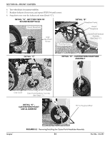
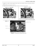
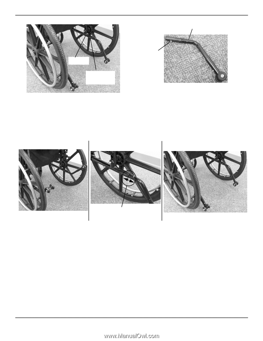
SECTION 10-ANTI-TIPPERS Anti-Tipper Step Tube Hole for Release Button Release Button FIGURE 10.1 Installing Anti-Tippers Changing Orientation of Anti-Tip Wheels NOTE: For this procedure, refer to FIGURE 10.2. 1. Pull the spring loaded anti tipper out and rotate up or down. 2. Rotate until anti‐tipper locks in the Up or Down position. Anti Tipper in Up Position Anti Tipper in Down Position Anti Tipper is spring loaded at this point FIGURE 10.2 Changing Orientation of Anti-Tip Wheels Part No. 1163197 39 Insignia™
-
 1
1 -
2
-
3
-
4
-
5
-
6
-
7
-
8
-
9
-
10
-
11
-
12
-
13
-
14
-
15
-
16
-
17
-
18
-
19
-
20
-
21
-
22
-
23
-
24
-
25
-
26
-
27
-
28
-
29
-
30
-
31
-
32
-
33
-
 34
34 -
 35
35 -
 36
36 -
 37
37 -
 38
38 -
 39
39 -
 40
40 -
 41
41 -
 42
42 -
 43
43 -
 44
44 -
45
-
46
-
47
-
48
-
49
-
50
-
51
-
52
 |
 |
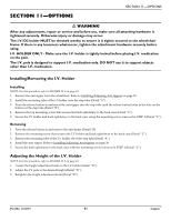
SECTION 10—ANTI-TIPPERS
Part No. 1163197
39
Insignia
™
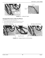
FIGURE 10.1
Installing Anti-Tippers
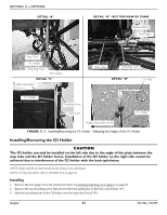
Changing Orientation of Anti-Tip Wheels
NOTE: For this procedure, refer to FIGURE 10.2.
1.
Pull the spring loaded anti tipper out and rotate up or down.
2.
Rotate until anti
‐
tipper locks in the Up or Down position.
FIGURE 10.2
Changing Orientation of Anti-Tip Wheels
Anti-Tipper
Release
Button
Step Tube
Hole for
Release Button
Anti Tipper in Down Position
Anti Tipper in Up Position
Anti Tipper is spring
loaded at this point