JVC GY-DV300U KA-DV300U/Streamproducer Quick Start Guide.
JVC GY-DV300U - 1/3" 3-ccd Dv Camcorder Manual
 |
View all JVC GY-DV300U manuals
Add to My Manuals
Save this manual to your list of manuals |
JVC GY-DV300U manual content summary:
- JVC GY-DV300U | KA-DV300U/Streamproducer Quick Start Guide. - Page 1
-Start For KA-DV300 firmware version 104 and Streamproducer 2.0 JVC wants you to get the most out of your GYDV300 with the KA-DV300 Network Pack. If you have any questions, concerns or problems, please feel free to contact our Network Product Specialist at: [email protected] Supported Accessory Cards - JVC GY-DV300U | KA-DV300U/Streamproducer Quick Start Guide. - Page 2
two seconds. Please refer to the Streamproducer Users Guide for instructions on streaming using Streamproducer Connecting with a Web Browser Connecting to the camera with A Web Browser supports the following features: • Real-time viewing of camera output, with audio. • Remote control and setup of
-
 1
1 -
 2
2
 |
 |
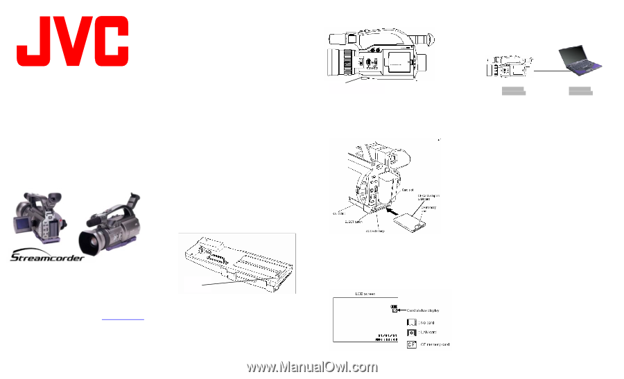
Release button
KA-DV300U /
Streamproducer
Quick-Start
For KA-DV300 firmware
version 104 and
Streamproducer 2.0
JVC wants you to get the most out of your GY-
DV300 with the KA-DV300 Network Pack.
If
you have any questions, concerns or
problems, please feel free to contact our
Network Product Specialist at:
Supported Accessory Cards:
•
Operating Voltage:
3.3 VDC
•
Max. Current:
300 mA @ 5V
As of October 2002, the KA-DV300 supports the following
accessory cards:
•
Wired LAN:
o
Socket Communications
(www.socketcom.com)
US:
EA2900-117 (Rev. C)
1
Europe:
EA2903-162 (Rev. C)
1
Asia:
EA2906-194 (Rev. C)
1
revision number on the upper-right of the
product label.
•
Wireless LAN:
o
TRENDNet (www.trendware.com)
TEW-16PC, revision 0.8.3 or later
(discontinued)
TEW-201PC
o
Linksys (www.linksys.com)
WCF11
2
•
CF Memory:
o
SanDisk (www.sandisk.com)
SDCFB-16 ~ SDCFB-256
1
1
– requires CF type I or type II to PCMCIA adapter
2
– requires CF Type II to PCMCIA adapter
Attaching the KA-DV300 to the GY-
DV300
1.
Insure that the GY-DV300 power is off.
2.
Slide the connector cover located on the bottom of the GY-
DV300 in the direction as shown by the arrow located next to
the connector cover.
3.
Align the hook on the KA-DV300 with the cutout on the rear
of the GY-DV300 below the battery compartment.
4.
Rotate the KA-DV300 upward toward the GY-DV300 until a
positive ‘click’ is heard and felt.
5.
To remove the KA-DV300 Network Pack, press the release
button on the front of the pack and pull away
from the
camera.
Inserting Accessory Card
1.
Insure that the GY-DV300 power is OFF.
2.
Insert the accessory card in the KA-DV300.
±
The card can only be inserted in one direction.
Do not
force the card into the slot.
3.
Turn on the power to the GY-DV300.
4.
The status of the inserted card is displayed on the LCD
and/or viewfinder screen.
NOTES:
•
When turning the power on, the card status display will
flash during initialization.
•
Inserting a card with the power ON may result in damage
to the card.
Wired Connections, Single Camera to
Single Computer
DHCP: OFF
DHCP: OFF
IP Address:
192.168.100.101
IP Address:
192.168.100.102
Netmask:
255.255.255.0
Netmask:
255.255.255.0
Both IP addresses must be within the same network group
and have the same subnet mask, as shown by the shading
above. In this example, the Network Group is 192.168.100.
When connecting directly from the camera to a computer,
operation is assured if the following conditions are met:
•
DHCP should be OFF.
•
If DHCP is off, the IP address of the camera and the
computer must be unique, but in the same Network
Group.
•
The Netmask of both the camera and computer
must be the same.
•
A CAT-5 crossover cable is used between the
camera and computer if no switch or hub is present.
•
Under most conditions, the computer LAN card
should be set for no proxy server. Please refer to
the KA-DV300 Users Guide for information
regarding this setting if troubles are encountered.
Wireless Connections, Single Camera
to Single Computer
In a similar manner to the wired connection, when connecting
directly from the camera to a computer using a wireless link
without an access point, operation is assured if the following
conditions are met:
•
DHCP must be OFF.
•
The IP address of the camera and the computer
must be unique, but in the same Network Group.
•
The Netmask of both the camera and computer
must be the same
•
set the WLAN AD HOC MODE to ON.
•
The WLAN ESS ID on both the KA-DV300 and the
computer must be the same.
The camera default
ESS ID is ‘wireless-lan’.
•
The KA-DV300 and the computer must be set to
use the same channel (WLAN CH).
•
Under most conditions, the computer LAN card
should be set for no proxy server. Please refer to
the KA-DV300 Users Guide ‘Setting a Proxy Server’
for information regarding this setting if troubles are
encountered.
Hook