JVC GY-DV700WU Specifications - Page 7
GY-DV700WU controls, indicators and connectors
 |
View all JVC GY-DV700WU manuals
Add to My Manuals
Save this manual to your list of manuals |
Page 7 highlights
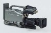
GY-DV700WU controls, indicators and connectors [Front section] 1 Viewfinder mount base, sliding securing ring 2 [VF] viewfinder connector (20-pin) 3 [MIC IN] microphone input connector (XLR 3-pin) 4 [LENS] lens control connector 5 [ZEBRA] switch 6 [VTR] trigger button 7 [AUDIO LEVEL CH-1] CH-1 recording level control 8 [AUTO WHITE/ACCU FOCUS] switch 9 [TAKE] button 0 Lens mounting ring/lens lock lever ! [FILTER] color temperature conversion filter control knob [Right side section - camera setting] @ [ALARM] volume control # [MONITOR] audio monitor volume control $ [STATUS] status/menu button % [SHUTTER/MENU] dial ^ [LOLUX] LOLUX on/off button & [BLACK] black stretch/black compression switch * [FULL AUTO] full auto shooting ON/OFF button and indicator ( [AUTO IRIS] auto iris level switch ) [GAIN] switch q [VTR SAVE/STBY] switch w [OUTPUT] color bar/camera/auto knee switch e [WHT.BAL] white balance switch r [NG] button t [POWER] switch [Right side section - audio setting] y Monitoring loudspeaker u [CH1 AUDIO LEVEL] CH1 recording level control i [CH2 AUDIO LEVEL] CH2 recording level control o [MONITOR SELECT] audio monitor selector switch p [CH-1 AUDIO SELECT] selector switch Q [CH-2 AUDIO SELECT] selector switch W [CH-1 AUDIO INPUT] selector switch E [CH-2 AUDIO INPUT] selector switch [Right side section - VCR setting] R [MENU] button T [HOLD/GROUP] button Y [SHIFT/ITEM] button U [ADVANCE/SELECT] button I [PRESET/DATA SET] button O [CONTINUE] button P [PRESET/REGEN] switch a [REC/FREE] run switch s Lithium battery installation compartment [Right side section - VCR display] d [OPERATE/WARNING] indicator f [RESET] button g [LIGHT] switch h [COUNTER] switch j Audio level meters k SP indicator l 32K/48K sampling frequency indication ; [AUD LOCK] indicator A [MENU] indicator S [WIDE] indicator D Cassette indicator F [REMAIN] indicator G Tape transport direction indicators H Remaining battery power display J Counter display K Time code-related indications (SLAVE/PB/HOLD) L Warning indicators (AUTO OFF/DEW/SERVO/RF/LI) / [Left side section] : Cassette cover z [MONITOR OUT] connector (BNC) x [Y/C OUT] connector (4P) c [TC IN] connector (BNC) v [TC OUT] connector (BNC) b [LINE OUT CH-1/CH-2) connector (RCA) n [TEST OUT] connector (BNC) m [SYNC IN] connector (BNC) , [VTR REMOTE] connector . Microphone attachment holes [Top section] / [EJECT] switch Z Operation cover X [PLAY] button C [STOP] button V [STILL] button B [REW] button N [FF] button M [LOG] button [Rear section] < [DV] connector > [EAR.] earphone jack ? [DC OUTPUT] connector ¡ [DC INPUT] connector (XLR 4-pin) ™ [CH-1 AUDIO IN] CH-1 audio input connector (XLR 3-pin) £ [CH-2 AUDIO IN] CH-2 audio input connector (XLR 3-pin) ¢ Back tally lamp ∞ [CH-1 AUDIO IN LINE/MIC] CH-1 AUDIO select switch § [CH-2 AUDIO IN LINE/MIC] CH-2 AUDIO select switch ¶ Battery holder • Battery holder lock release knob ª [BREAKER] Z % $ ( * q r t y @ # . & ^ ) w e : x z c vb ,m n 34 5 6 M f dl BC kj NXV LK g ; A h osD F GHJ pQ Pa O R I us i W TE Y U • 1 2 ¶ ! 0 ∞ < § 9 8> ¢ ? 7 ª¡ ™ £
-
 1
1 -
 2
2 -
 3
3 -
 4
4 -
 5
5 -
 6
6 -
 7
7 -
 8
8
 |
 |
