JVC KS-AR9501D Instructions - Page 3
Wired remote control unit: RM-RK130 purchased separately, TROUBLESHOOTING, SPECIFICATIONS, CONTROLS
 |
UPC - 046838037528
View all JVC KS-AR9501D manuals
Add to My Manuals
Save this manual to your list of manuals |
Page 3 highlights
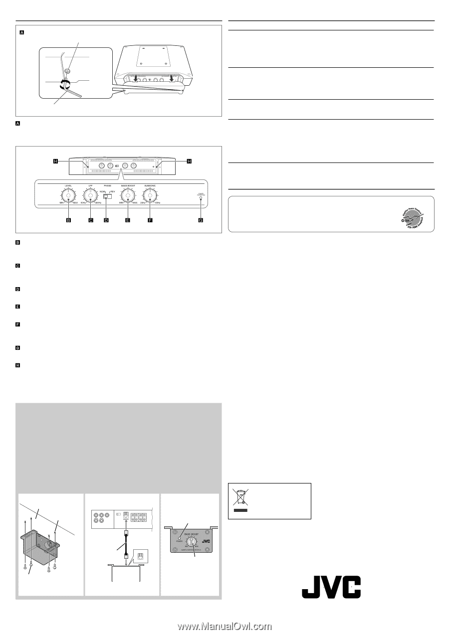
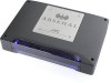
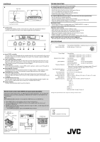
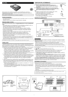
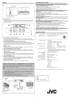
CONTROLS Hex screw Hex wrench (2.5 mm) Control cover To operate the following controls, remove the hex screws with a provided hex wrench (2.5 mm) and detach the control cover. Attach it again after your operation. TROUBLESHOOTING For more details, consult your JVC car audio dealer. The POWER/PROTECTOR lamp does not light. • Change the fuses if the current one is blown. • Connect the ground lead securely to a metal part of the car. • Turn on the equipment connected to this unit. • Use a relay if your system employs too many amplifiers. • Confirm the battery voltage (11 V to 16 V). The POWER/PROTECTOR lamp lights in red and/or the unit heats up abnormally. • Use the speakers of suitable impedance. • Correct the speaker wirings if they are short-circuited. • Make the speaker wirings away from the power cord to prevent DC offset error. • Leave the unit turned off for a while to cool it down. No sound is heard. • Confirm the connections for power supply (see "POWER SUPPLY" on page 1). • Connect RCA pin cords to the INPUT jacks firmly. Alternator noise is heard. • Keep the power cords away from the RCA pin cords. • Keep the RCA pin cords away from other electrical cables in the car. • Connect the ground lead securely to a metal part of the car. • Make sure the negative speaker leads do not touch the car chassis. • Replace the plugs or use plugs with load resistors. • Connect a bypass capacitor across the accessory switches (horn, fan, etc.). Noise is made when you connect the unit to an AM tuner. • Move the speaker and power cords away from the antenna lead. SPECIFICATIONS Power Output Signal-to-Noise Ratio • Normal Mode: 500 W RMS x 1 channel at 4 Ω and ≤ 1% THD + N 60 dBA (reference: 1 W into 4 Ω) Input LEVEL controller The input level can be adjusted with this controller when this unit is connected to other source equipment. Adjust the level while listening to the sound. This controller is preset to MIN when the unit is shipped. LPF (Low-Pass Filter) controller Adjust the cutoff frequency (the Low-Pass Filter transmits frequencies lower than the cutoff frequency) within the range of 50 Hz to 300 Hz. Adjust the level while listening to the sound. This controller is preset to 50 Hz when the unit is shipped. PHASE switch Select either normal (NOM) or reverse (REV), which reproduce a better sound. This switch is preset to NOM when the unit is shipped. BASS BOOST controller Turning this boosts the 45 Hz frequency within the range of 0 dB to +18 dB. Adjust the level while listening to the sound. This controller is preset to MIN when the unit is shipped. SUBSONIC filter controller Adjust the cutoff frequency (the subsonic filter rejects frequencies lower than the cutoff frequency) within the range of 20 Hz to 50 Hz. This controller is preset to 20 Hz when the unit is shipped. POWER/PROTECTOR lamp The lamp lights in green while the unit is turned on. If the lamp does not light or lights in red with the unit on, some trouble has occurred (see "TROUBLESHOOTING"). Power indicator The blue lamp illuminates while the unit is turned on. Wired remote control unit: RM-RK130 (purchased separately) Using JVC's wired remote control unit: RM-RK130 (purchased separately), you can adjust the bass boost in your seat without adjusting the BASS BOOST controller on the amplifier (see "CONTROLS"). Note Set the BASS BOOST controller on the amplifier to MIN when you use RM-RK130. Power Output Maximum Power Output Load Impedance Frequency Response Input Sensitivity/Impedance Distortion Power Requirement Grounding system Dimensions (W×H×D) Mass (approx.) Supplied Accessories • Normal Mode: 1 000 W RMS x 1 channel at 2 Ω and ≤ 1% THD + N 1 500 W RMS x 1 channel at 1 Ω and ≤ 1% THD + N • Normal Mode: 1 800 W • External Bridge Mode: 3 000 W • Normal Mode: 4 Ω (1 Ω to 8 Ω allowance) • External Bridge Mode: 2 Ω (2 Ω to 8 Ω allowance) 20 Hz to 300 Hz* (+0, -3 dB) * Subsonic filter cuts off extremely low frequency signals. (The cutoff frequency is adjustable within the range of 20 Hz to 50 Hz.) 2 V/45 kΩ (0.3 V to 6 V, variable) Less than 0.1% (at 100 Hz) DC 14.4 V (11 V to 16 V allowance) Negative ground 360 mm × 60 mm × 245 mm (14 3/16 inch × 2 3/8 inch × 9 11/16 inch) 5.00 kg (11.02 lbs.) Screw-Dia. 4 mm (3/16 inch) × 20 mm (13/16 inch) × 4 Hex wrench 4 mm × 1 3 mm × 1 2.5 mm × 1 Spacer × 4 Bracket × 2 Hex screw-M4 × 12 mm (1/2 inch) × 6 Design and specifications are subject to change without notice. A Mount RM-RK130 on a firm surface, such as under the dashboard. B Connect RM-RK130 to the REMOTE terminal on the amplifier with the remote cord provided for RM-RK130. C RM-RK130 boosts the 45 Hz frequency within the range of 0 dB to +18 dB. Adjust the level while listening to the sound. • The POWER lamp lights in green while RM-RK130 is turned on. A B Under the dashboard, etc. Drilled hole C POWER lamp [European Union only] Remote cord (provided for RM-RK130) Screw-Dia. 4 mm (3/16 inch) × 12 mm (1/2 inch) (provided for RM-RK130) RM-RK130 BASS BOOST controller 3
-
 1
1 -
 2
2 -
 3
3 -
 4
4 -
 5
5 -
 6
6
 |
 |